
op amp Crystal Oscillator with OP AMP or Oscillator circuit built with Crystal and Op Amp

An oscillator circuit utilizing an operational amplifier (op-amp) and a crystal can be effectively designed to generate a stable frequency output. The 7.68 MHz crystal will serve as the frequency-determining element in this configuration. The basic principle behind the oscillator is to achieve positive feedback, which is essential for sustained oscillations.
To construct the oscillator, the following components will be necessary:
1. **Operational Amplifier:** A suitable op-amp should be selected based on the required bandwidth and slew rate. Common choices include the TL081 or LM358, provided they can handle the frequency in question.
2. **Crystal:** The 7.68 MHz crystal will be connected to the op-amp in a manner that allows it to set the oscillation frequency. The crystal will typically be connected in a feedback loop.
3. **Resistors:** Two resistors will be required to set the gain of the op-amp. The feedback resistor (Rf) will be connected between the output and the inverting input of the op-amp, while the input resistor (Rin) will connect the inverting input to ground. The ratio of these resistors will determine the gain and stability of the oscillator.
4. **Capacitors:** Two capacitors will be used in the circuit. The first capacitor (C1) will be connected in parallel with the crystal to stabilize the oscillation frequency, while the second capacitor (C2) will be connected to the non-inverting input of the op-amp to help filter noise and improve stability.
The configuration will typically follow these steps:
- Connect the crystal between the output and the inverting input of the op-amp.
- Connect C1 in parallel with the crystal.
- Connect Rf from the output of the op-amp to the inverting input and Rin from the inverting input to ground.
- Connect C2 from the non-inverting input to ground, ensuring that the op-amp has a proper reference voltage.
The resulting circuit will allow the op-amp to amplify the feedback signal from the crystal, thus generating a stable oscillation at the desired frequency of 7.68 MHz. Proper power supply decoupling should also be considered to ensure stable operation of the op-amp.
In conclusion, it is indeed possible to create an oscillator circuit using a 7.68 MHz crystal, capacitors, resistors, and operational amplifiers, provided that the circuit is designed with careful consideration of component values and configuration.Make a Oscillator circuit with a Op Amp and an crystal (7. 68 MHz) Similar to the one in the schematic below, but for a 7. 68 MHz crystal. I have the crystal, various Capacitors, Resistors and a couple of Op Amps. But no digital Logic chips. "LM111 is not an op-amp", is it even possible I make an oscillator then from just from acrystal, capacitors, resistors, and some op amps If you need more details on the parts, i can list them completely RMDS 🔗 External reference
Related Circuits
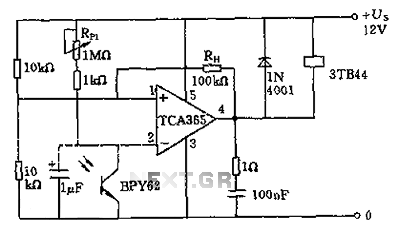
A bridge input circuit utilizing a phototransistor BPY62 and a power operational amplifier is capable of controlling power loads up to 8.5 kW. It features a voltage divider composed of two 10 kΩ resistors, creating a midpoint connection. The...
The objective is to design a square-wave generator with an output range of 0 to +5V. Additionally, the design should allow for the modification of the signal to enable adjustment of the duty cycle of the pulse (PWM). The square-wave...
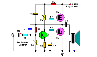
This project includes a preamplifier, tone controls, a regulated DC power supply, and delivers 18 watts into an 8-ohm load and 30 watts into a 4-ohm load. The circuit design comprises several key components that work together to create...
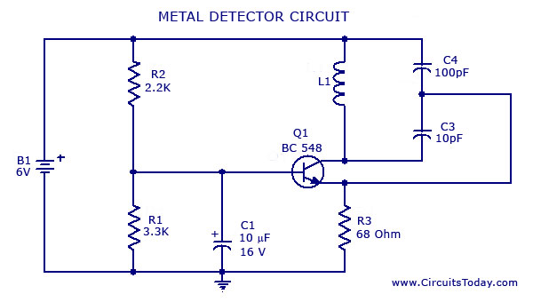
A simple metal detector circuit diagram and schematic using a single transistor and a radio. This metal detector/sensor project is easy to make and is an application of a Colpitts oscillator. The metal detector circuit utilizes a single transistor in...
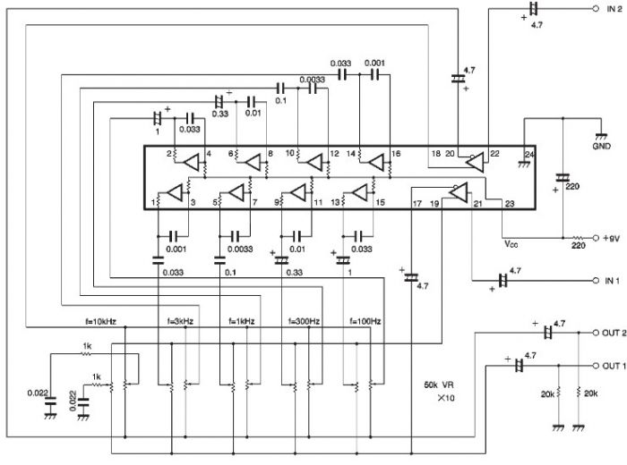
The BA3822 is a five-point stereo graphic equalizer integrated circuit that operates with two channels. Each channel can independently set five center frequencies using external capacitors. This integrated circuit supports a wide operating power supply voltage range (VCC =...
The sound system features a de-sensitized design with a maximum range that can be increased if desired. It includes two tone controls: one offering a lift of 10 dB and the other providing a subtle cut of 3 dB....