
555 dual astable multivibrator circuit diagram

The described circuit utilizes two 555 timer ICs configured in astable mode, allowing for continuous oscillation and generation of pulse signals. Each timer operates independently but is synchronized to ensure that the output signals maintain a specific phase relationship. The frequency of oscillation is primarily determined by the resistors and capacitors connected to each timer. In this configuration, the timing components (R1, R2, and C1 for the first timer, and R3, R4, and C2 for the second timer) can be adjusted to modify the frequency and duty cycle of the output signals.
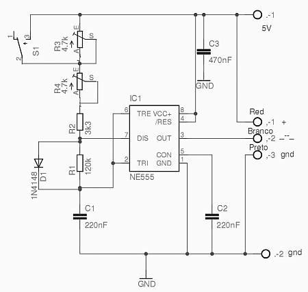
When both capacitors (C1 and C2) are equal, the oscillation frequency of the circuit can be expressed by the formula:
\[ f = \frac{1.44}{(R1 + 2R2)C} \]
This indicates that by changing the values of R1, R2, and C, the frequency can be fine-tuned to meet specific application requirements. The duty cycle can also be calculated using the formula:
\[ D = \frac{R2}{R1 + 2R2} \]
where D represents the duty cycle as a percentage. This flexibility allows for a variety of applications, including signal generation, clock pulses for digital circuits, and timing applications.
The circuit's design ensures that the output signals are synchronized, which is crucial for applications that require precise timing between multiple signals. The 555 timer's reliability and ease of use make this configuration suitable for both educational purposes and practical implementations in various electronic projects. Additionally, the ability to easily modify component values makes this circuit adaptable to different operational conditions and requirements.The circuit includes two synchronized multivibrators which are composed ofone pair of 555time base circuits. The circuit can output two synchronized pulse signals,and the spacing and frequency can be changed by adjusting the time constant.
The circuit is flexible and convenient. When C1=C2=C, the oscillation frequency. The ducy cycle depends on the v.. 🔗 External reference
Related Circuits

The term "pentester" refers to a penetration tester, individuals who assess security vulnerabilities. Many high-end hotels globally depend on keycard locks for securing hotel rooms. However, recent incidents of theft have shown that these locks may not be as...
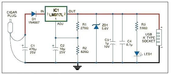
USB car charger adapter circuit design using LM317 regulator circuit The USB car charger adapter circuit utilizing the LM317 voltage regulator is designed to convert a car's 12V DC power supply into a stable 5V output, suitable for charging USB-powered...
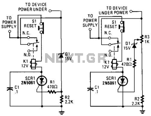
If circuits experience frequency overvoltage conditions, continually replacing blown fuses can become quite costly. This shutdown circuit addresses that issue by substituting the fuse with a relay and a low-current SCR. When the input voltage exceeds the threshold established...
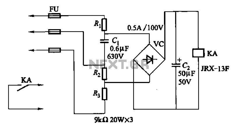
A capacitor C1 and resistors R1-R3 form a negative sequence voltage filtration device. The resistors and capacitors must meet the following requirements: R1, R2, R3 = 5.5/C1 (KN). The relationship between the resistance and capacitance values is arbitrary. Capacitor...
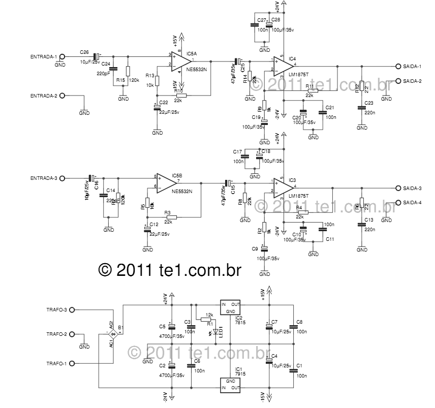
The LM1875 delivers 20 watts into a 4 or 8-ohm load on ±25V supplies. Using an 8-ohm load and ±30V supplies, over 30 watts of power may be delivered. The amplifier is designed to operate with a minimum of...
This circuit is designed to test the servo motor of a parabolic antenna. It functions effectively, although a system with a low-noise block feed (LNBF) is generally more suitable. Many users continue to utilize systems that employ an LNB...