
USB car charger adapter circuit design
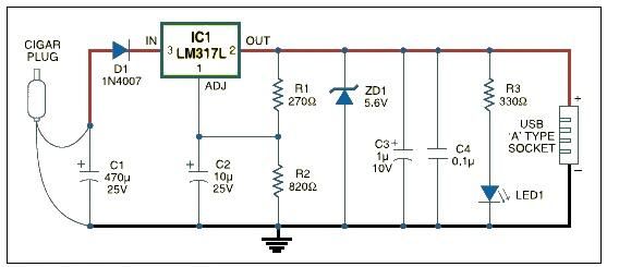
The USB car charger adapter circuit utilizing the LM317 voltage regulator is designed to convert a car's 12V DC power supply into a stable 5V output, suitable for charging USB-powered devices. The LM317 is a versatile adjustable voltage regulator that can provide a constant output voltage with a load current of up to 1.5A, making it ideal for charging applications.
In this circuit, the input voltage from the car battery (typically ranging from 12V to 14.4V) is fed into the LM317. The output voltage is set to 5V by using two external resistors connected to the adjustment pin of the LM317. The values of these resistors determine the output voltage according to the formula:
Vout = Vref (1 + R2/R1) + Iadj * R2
Where Vref is typically 1.25V. By selecting appropriate resistor values, the output can be accurately adjusted to 5V.
To ensure proper operation and stability, capacitors are placed at both the input and output of the LM317. A 0.1µF ceramic capacitor is recommended at the input to filter out any high-frequency noise, while a larger electrolytic capacitor (typically 10µF or more) is placed at the output to smooth the voltage and provide transient response during load changes.
Additionally, a heat sink may be necessary for the LM317 to dissipate heat generated during operation, especially when the input voltage is significantly higher than the output voltage. The circuit is typically enclosed in a compact housing with a USB output port for convenience, allowing users to easily connect and charge their devices.
Protection features such as a fuse or a resettable polyfuse can be included to prevent overcurrent conditions, ensuring the safety and reliability of the charger. The design can be further enhanced with LED indicators to show the charging status of the connected device. Overall, the LM317-based USB car charger circuit is an efficient and cost-effective solution for powering USB devices from a vehicle's electrical system.USB car charger adapter circuit design using LM317 regulator circuit 🔗 External reference
Related Circuits
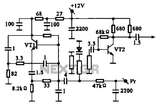
The local oscillator operates at frequencies of 1 GHz or higher, utilizing a common collector circuit, which makes it challenging to generate low-frequency self-oscillation. Typically, the local oscillator signal is passed through a buffer amplifier stage before being applied...
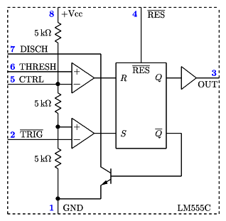
It is a typical Astable Multivibrator (AMV) setup. The capacitor charges through both resistors until it reaches 2/3 of Vcc, which is the level of the internal comparator. This triggers a flip-flop, activating the Discharge output (DIS). The capacitor...
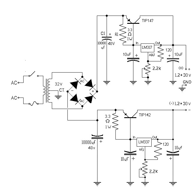
The 10A variable power supply circuit is symmetrical and can provide a symmetrical output voltage ranging from ±1.2 volts to ±30 volts DC, with a maximum current of 10A. This circuit utilizes symmetrical variable voltage regulators LM317 and LM337,...

The schematic includes programmable AVRs. For other members of the AVR family or additional programmable ICs compatible with Ponyprog, there is a J1 connector (CON10) that facilitates hardware expansion of the programmer. Additional information about compatible ICs can be...

This device offers numerous implementation possibilities due to its wide input voltage range and large maximum output current across a broad output voltage spectrum. It features long battery life and low power consumption owing to its high efficiency and...
Here, S1 and S2 are normally open, push to close, press button switches. The diodes can be red or green and are there only to indicate direction. You may need to alter the TIP31 transistors depending on the motor...