
555 IC LED Flasher for Up To 10 LEDs

The LED flasher circuit based on the 555 timer IC is a versatile and efficient design suitable for various applications, including decorative lighting, indicators, and signaling devices. The 555 timer can be configured in astable mode to create a pulsing LED effect.
In this configuration, the circuit consists of a 555 timer, resistors, capacitors, and LEDs. The timer generates a square wave output, which alternates between high and low states, causing the connected LEDs to flash on and off. The frequency of the flashing can be adjusted by varying the resistor and capacitor values connected to the 555 timer.
The circuit typically includes two resistors (R1 and R2) and a capacitor (C1) connected to the discharge and threshold pins of the 555 timer. The time period for which the output remains high (on) and low (off) can be calculated using the formula:
\[ T = 0.693 \times (R1 + 2R2) \times C1 \]
This formula allows for precise control over the flashing rate. For instance, increasing R1 or R2 will result in a longer on-time, while increasing C1 will also extend the duration of the flash.
The output pin of the 555 timer can drive a transistor to control larger currents, allowing the circuit to power multiple LEDs. When multiple LEDs are connected in series, the total forward voltage drop across the LEDs must be considered to ensure that the supply voltage is sufficient. However, the overall power consumption remains manageable, as the series configuration does not increase the total current drawn from the power supply.
In summary, this LED flasher circuit is an efficient design that leverages the capabilities of the 555 timer IC to provide a reliable and adjustable flashing LED output. The ability to connect multiple LEDs in series without increasing power consumption makes it a practical choice for various electronic projects.This LED flasher circuit uses 555 IC, and is capable of driving up to LEDs. The good news is, the use of multiple LEDs in series doesn`t increase the power.. 🔗 External reference
Related Circuits
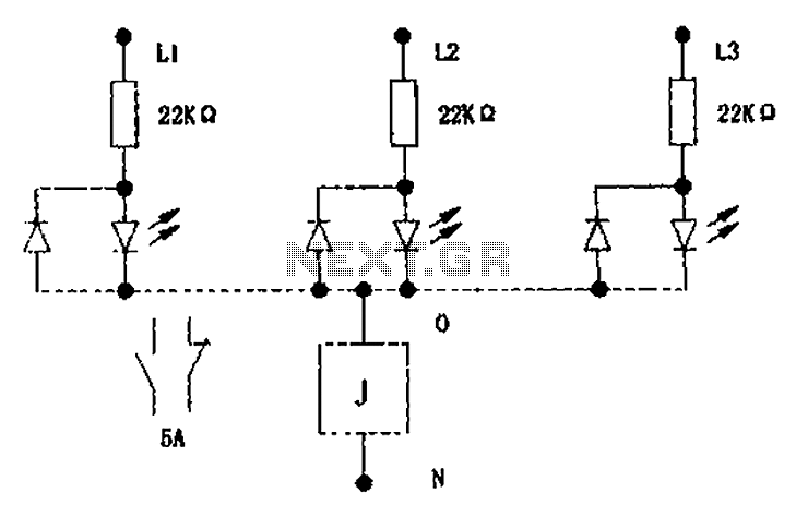
The circuit illustrated below activates a small relay (J) when there is an imbalance in any one phase of a three-phase circuit. This relay triggers an external control contact, which immediately disconnects the power supply to the main circuit...

This is a VU meter circuit featuring 10 LEDs. This simple LED VU meter consists of only a few components, yet it serves as an effective indicator for sound levels. The circuit is constructed around an unspecified component. The VU...

The SE555/NE555 timer was first introduced by the Signetics Corporation around 1971. Pin connections and functions are as follows: Pin 1 (Ground) - This pin serves as the ground or common pin, representing the most negative supply potential of...
This circuit is suitable for a small office or home environment. It can also be adapted to use a combination lock or keypad for setting and resetting. The described circuit functions as a security system tailored for small office or...
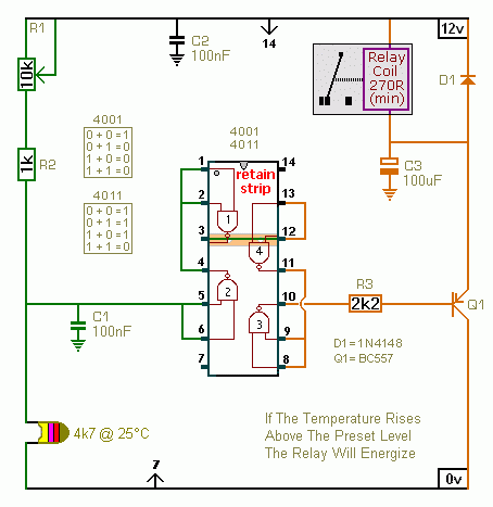
A CMOS 4001 or a CMOS 4011 can be utilized in this circuit, as both contain four two-input gates. The inputs of each gate are connected together, allowing them to function as simple inverters. This means that when both...

This sign design does not utilize a microprocessor. Instead, it employs an EPROM and multiple counters. Similar to most electronic signs, the LEDs are arranged in a matrix and are stroboscopically activated at a high frequency to create the...