
Astable circuits produce pulses using 555
The SE555/NE555 timer is a versatile integrated circuit widely used in various applications such as timers, pulse generation, and oscillators. The device operates in different modes, including monostable, astable, and bistable configurations.
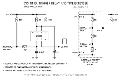
In the monostable mode, the timer produces a single output pulse in response to a trigger signal. The duration of the output pulse is determined by an external resistor and capacitor connected to the timer. The time period can be calculated using the formula: T = 1.1 * R1 * C1, where T is the pulse duration, R1 is the resistance in ohms, and C1 is the capacitance in farads.
In astable mode, the SE555 timer operates as an oscillator, generating a continuous square wave output. The frequency and duty cycle of the output waveform can be adjusted by varying the values of two external resistors (R1 and R2) and a capacitor (C1). The frequency can be calculated using the formula: f = 1.44 / ((R1 + 2 * R2) * C1), while the duty cycle can be expressed as: Duty Cycle = (R2 / (R1 + 2 * R2)) * 100%.
The bistable mode allows the SE555 to act as a flip-flop, where the output state can be toggled between high and low states by applying trigger signals to the appropriate pins.
The device features a reset pin (Pin 4), which can be used to terminate the timing cycle prematurely, and an output pin (Pin 3) that provides the timed output signal. The SE555 timer is capable of sourcing or sinking up to 200 mA of current, making it suitable for driving various loads directly.
Overall, the SE555/NE555 timer is a robust and reliable component that is integral to many electronic designs, providing precise timing and waveform generation capabilities.First introduced by the Signetics Corporation as the SE555/NE555 about 1971. Pin connections and functions: (See schematic below for basic circuits) Pin 1 (Ground) - The ground (or common) pin is the most-negative supply potential of the device, which is normally connected to circuit common when operated from positive supply voltages. Pin 2 (Trigger) - This pin is the input which causes the output to go high and begin the timing cycle.
Triggering occurs when the trigger input moves from a voltag. 🔗 External reference
Related Circuits
The IRF820 MOSFET has a voltage rating of 500V; it should work well in preamp stages of most tube amps. The 100-ohm resistor is there to suppress H.F. oscillations. If the IRF820 is physically close to the 12AX7 plate,...
The phone system used to be operated by a human operator in a telephone exchange room. The caller would pick up the phone and give instructions to the operator to connect their line to the destination on the other...

This is an application circuit for calibration known as a high voltage AC calibrator circuit. An essential aspect of sine wave oscillator design is the stable control of amplitude. This circuit not only stabilizes the amplitude through servo control...
This project is a successor to SSTC1, which has been retired. The purpose of this coil is to operate with its breakout suppressed, demonstrating the concept of wireless power that Tesla himself worked on during his time. Further videos...
The following circuit illustrates a Set Timing Calculator Circuit. This circuit is based on the LM555 integrated circuit. Features include the provision of a delay of approximately... The Set Timing Calculator Circuit utilizing the LM555 integrated circuit (IC) is designed...
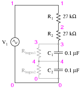
Construct the circuit and measure the voltage drops across each component using an AC voltmeter. Additionally, measure the total (supply) voltage with the same voltmeter. It will be observed that the individual voltage drops do not sum up to...