
led sign

The electronic schematic for the described sign consists of several key components that facilitate its operation. The EPROM, functioning as the primary memory unit, stores the binary data corresponding to the messages and animations to be displayed. The 27C512 EPROM is particularly suitable for this application due to its capacity of 64k bytes, allowing for extensive message storage. The 8 outputs from the EPROM are critical in controlling the LED matrix; 7 outputs are dedicated to driving the horizontal rows, while the 8th output is responsible for resetting the counters, ensuring a seamless loop of the displayed content.
Buffering is implemented for the EPROM outputs to amplify the signal strength, which is necessary for driving the LED matrix effectively. The vertical columns are activated in a sequential manner, which is achieved through a series of counters that control the timing of each column's illumination. This method ensures that only one column is active at a time, resulting in a duty cycle of 1/10, which is efficient for power consumption while maintaining visibility.
The use of decoupling capacitors is essential in this circuit to stabilize the power supply and reduce noise, which can adversely affect the performance of the EPROM and LED matrix. The recommended placement of 0.1uF capacitors throughout the circuit helps to filter out high-frequency noise and provides a stable voltage supply to the sensitive components.
The programming aspect of the design involves the creation of a message compiler and an animation tool, which are essential for generating the binary files that the EPROM utilizes. The font map allows for the display of characters in a recognizable format, while the animation program provides flexibility in designing dynamic messages.
Overall, this electronic sign design demonstrates a practical application of EPROM technology and LED matrix control, showcasing how efficient programming and circuit design can produce visually appealing results without the complexity of microprocessor-based systems.This sign I designed uses no microprocessor. It has an eprom and multiple counters. As in most electric signs, the LEDs are matrixed, and strobed very quickly to make it possible for all 70 LEDs to appear lit. This sign is strobed horizontally, unlike most large signs which are strobed vertically. I did it this way because electrically it was simp ler. The eprom has 8 outputs, of which I used 7 of them to drive the 7 horizontal rows. The eprom outputs are not strong, so they are buffered. The 10 vertical columns are activated in sequence, giving a 1/10 duty cycle. I used the 8th output of the eprom to drive the reset for all the counters, so the circuit loops when empty memory is reached, allowing for short or long messages. With a 27C512 eprom(64k bytes), messages and animations can be almost a minute long! Filling 65536 bytes of memory is easy, but "quality time" takes some programming. I wrote a little message compiler program that produces binary files compatible with an eprom programmer.
The first program I wrote(the latest version is cgrom7. exe) allows you to write a message or import a text file. It uses a font map(cgrom. dat) that I created. The letters look like standard 5x7 dot matrix letters. Not quite two letters fit side by side on the display, because I allowed a one-pixel wide column between each letter. The effect is quite pleasing, because the message moves horizontally one pixel at a time(In truth, each frame is displayed several times before it moves).
The second program I wrote(romart03. exe) is a paint and animation program. You "light up" pixels on a large screen and have a 7x10 window that you can move around, and write frames to a binary file as you choose. The program does a couple of other things that allow you to chain files together, etc. I put the two programs together along with the font file into a zip file you`ll want to get if you build a sign of your own.
While you`re at it, take a look at the schematic diagram of the circuit. Please note that this schematic has a lot of my shorthand and will be undecipherable by all but the most savvy. Important Construction Note: The use of decoupling capacitors(not shown in the schematic) is not optional!
Spread three or four 0. 1uF caps throughout the circuit. Update! Thanks to Jon Renck, I can present a better schematic. John "unrolled the loops" and drew a complete schematic, and I fixed a couple of confusing points, and here it is. sign2jr. gif, you might want to download it rather than viewing it online. Although only 63K, it is a multi-megapixel bitmap and will crash some browsers. 🔗 External reference
Related Circuits
The table provided is useful for determining the capabilities of the MOSFETs across various versions. However, the connectors used in the LED3X "c" series are not rated for high continuous currents; they are technically rated for 7 amps. While...

This is a compact LED flasher circuit designed using the 555 timer integrated circuit (IC), powered by two 1.5V batteries. The circuit can function as a flashing metronome, dark room timer, reminder, or for other similar applications. In the...
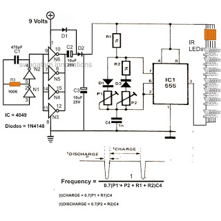
The 4049 section serves as a fundamental voltage doubler circuit, enhancing a 9 V supply to approximately 15 V. This elevated voltage subsequently acts as the supply voltage for the following 555 pulse modulator section. A key characteristic of...
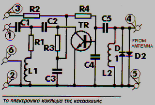
These frequencies include TV in VHF and UHF, as well as the radio broadcasting frequencies in the 88 - 108 MHz FM band. Component: Resistor, IC. The circuit described operates within the VHF (Very High Frequency) and UHF (Ultra High...
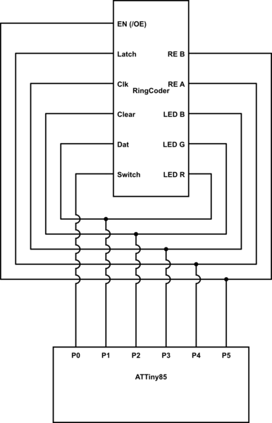
A chip conversion is being performed for the Sparkfun LED RingCoder. The sample code provided with the product functions effectively on an Arduino UNO, utilizing a separate pin for each input/output—specifically, five pins for the shift registers and six...
This circuit when used with a 555 timer will cause light emitting diodes to turn on and off more slowly. This will make the LEDs appear similar to incandescent lamps. The described circuit utilizes a 555 timer IC configured in...