
555 Infrared Transmitter-Receiver

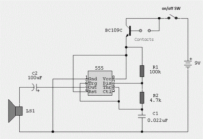
The infrared transmitter and receiver circuit is designed to facilitate wireless communication through infrared signals, making it suitable for remote control applications. The transmitter section typically consists of an infrared LED that emits modulated light signals. This modulation is achieved using an oscillator circuit, which generates a square wave signal at a specific frequency. The modulation frequency is crucial as it helps in distinguishing the transmitted signals from ambient infrared noise.
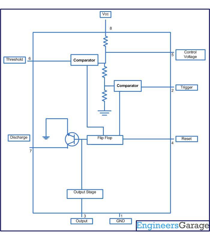
The oscillator circuit can be constructed using a 555 timer IC or a similar configuration of transistors and passive components. The output from the oscillator drives the infrared LED, causing it to emit pulses of infrared light. The modulation frequency is selected based on the requirements of the remote control application, often falling within the range of 36 kHz to 40 kHz for effective performance.
On the receiver side, an infrared photodiode or phototransistor is employed to detect the emitted infrared signals. When the photodiode receives the modulated light from the transmitter, it generates a corresponding electrical signal. This signal is then processed by an amplifier circuit to enhance its strength. The amplified signal can be further demodulated to retrieve the original control information, which can be used to drive various electronic components or systems, such as motors or relays.
In summary, the infrared transmitter and receiver circuit serves as a fundamental building block for remote control systems, utilizing modulation techniques to ensure reliable communication through infrared light. The choice of components and configuration will depend on the specific application requirements, including range, power consumption, and response time.Infrared transmitter and receiver circuit shown in the schematic diagram below can be used as remote control. The transmitter is basically an oscillator.. 🔗 External reference
Related Circuits
This circuit-based project demonstrates the operation of a 555 timer in astable mode to generate pulses with a time period of 0.5 seconds. These pulses can be utilized in various applications, such as blinking an LED or creating decorative...
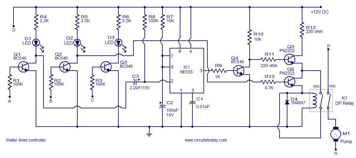
A simple water level controller circuit utilizing a 555 integrated circuit (IC) and six transistors. A relay is employed for controlling the pump motor. This water level controller circuit is designed to monitor and manage the water level in a...
A 12V to 20000V inverter circuit diagram (stun gun) is presented. This circuit generates a very high voltage and must be used with caution to prevent electric shock. The transformer can produce over 1000V and amplify the voltage by...
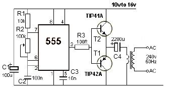
This 12V power inverter circuit can be utilized to power small devices that require 240 volts. It is particularly advantageous for operating 240-volt appliances using a 12-volt car battery. Unlike typical feedback oscillator inverters, this design employs a 555...
It allows car headlights to flash on and off simultaneously or alternately. Components: 555 IC, transistor, resistor, relay, polarized capacitor. The circuit utilizes a 555 integrated circuit (IC) in a monostable or astable configuration to control the flashing of car...
Probes or contacts may utilize a non-reactive metal. Gold or silver plated contacts from an old relay may be used; however, a cost-effective alternative is to wire alternate copper strips from a piece of veroboard. These will eventually oxidize,...