
12V power inverter using 555 timer circuit
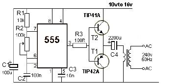
This 12V power inverter circuit is designed to convert a low-voltage DC input into a higher-voltage AC output, making it suitable for powering standard household appliances from a car battery. The use of a 555 timer as an astable multivibrator is a notable feature of this circuit. This configuration allows for precise control over the frequency of the output waveform, which can be adjusted according to the needs of different devices.
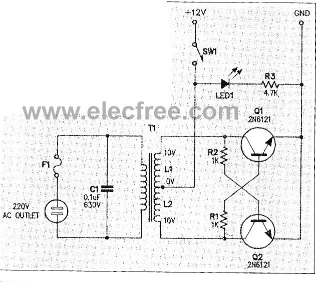
The circuit begins with the 555 timer, which generates a square wave signal at a frequency determined by the values of the resistors and capacitors connected to it. This square wave signal is then used to drive the base of the transistors T1 and T2, which function as switches. When activated, these transistors allow current to flow through the primary winding of the output transformer, inducing a high-voltage AC signal in the secondary winding.
The output transformer plays a crucial role in stepping up the voltage from 12V to the desired 240V. The specifications of the transformer, including its turns ratio and core material, will significantly influence the efficiency and performance of the inverter. Additionally, the choice of driver transistors (T1 and T2) will determine the maximum load the inverter can handle, as their current and voltage ratings must be suitable for the intended application.
To ensure stable operation and prevent damage during load variations, it is advisable to include protective components, such as fuses or circuit breakers, in the design. Furthermore, incorporating filtering capacitors at the output can help smooth the waveform and reduce ripple, resulting in a cleaner AC signal.
Overall, this 12V power inverter circuit represents an effective solution for powering 240V devices from a 12V source, offering flexibility and adaptability for various applications.This 12V power inverter circuit can be used to power small power devices that need a 240 volts. This 12V power inverter circuit is very useful when you want to use a 240 volts consumer powered by a 12 volts car battery. In contrast to the usual feedback oscillator type of inverter, the oscillator of this inverter use a 555 timer connected as an
astable multivibrator that is separate from the output stage, which allows easy adjustment of the oscillator frequency to suit different applications. The output of the 555 timer drives the base of T1 and T2 transistors. The wattage of this 12 volts inverter circuit depend on the driver transistors and the output transformer used.
The output of this circuit will provide a 240v at 50Hz. 🔗 External reference
Related Circuits
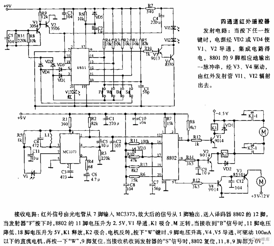
The receiving circuit involves an infrared signal being input to the MC3373 from pin 7 via a phototube. The amplified signal is output from pin 1 and sent to pin 12 of the decoder 8802. When the transmitter F...
This is the large controller utilized for the game Steel Battalion for the Xbox. The schematic diagram was sourced from an individual named Alpha who created it for his own use. The Steel Battalion controller is a specialized input device...
The 555 timer generates positive pulses. The pulse width is inversely proportional to the difference in voltage between the "ANALOG IN" voltage and the voltage across a 4.7 µF capacitor (approximately 2.5 volts). To calibrate this circuit, connect it...
This micro inverter is a small-sized device that modifies energy from a battery, producing an output voltage of approximately 220V AC at 50Hz. The circuit comprises two transistors that function as a pulse oscillator or square wave generator, driving...
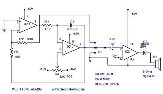
A simple alarm circuit with a diagram and schematic that generates a multi-tone sound. This alarm circuit is suitable for use in burglar alarms and sirens and is designed using dual op-amps MC1458 and LM380. The described alarm circuit utilizes...
In the first circuit, the BC548 transistor is configured as a Colpitts oscillator, with the frequency being adjusted through the insertion of a crystal. A high-quality crystal will generate high-frequency oscillations, and the output at the collector is rectified...
Warning: include(partials/cookie-banner.php): Failed to open stream: Permission denied in /var/www/html/nextgr/view-circuit.php on line 713
Warning: include(): Failed opening 'partials/cookie-banner.php' for inclusion (include_path='.:/usr/share/php') in /var/www/html/nextgr/view-circuit.php on line 713