
555 LED flasher II
The described circuit utilizes the popular 555 timer IC configured in astable mode to create a flashing light effect suitable for bicycle safety. The power supply consists of three C or D cells providing a total of 4.5 volts, which is adequate for operating the circuit and the connected lamps. The timing components include a 4.7K ohm resistor (R1) and a 100K ohm resistor (R2), along with a 4.7 microfarad capacitor. These values are carefully chosen to achieve the desired flashing rate, with the upper lamp flashing for approximately 341 milliseconds and the lower lamp for about 326 milliseconds, resulting in a near 1.5 second cycle time for both lamps.
Transistors are employed to handle the higher current requirements of the lamps, which exceed the 200 mA output limit of the 555 timer. The circuit can accommodate lamps with a current draw of up to 500 mA by using a 2N2905 PNP transistor for the upper lamp and a 2N3053 NPN transistor for the lower lamp. For applications requiring even more current, such as lamps drawing up to 1 amp, the circuit can be modified to include TIP29 and TIP30 transistors.
The PR3 flashlight bulb, rated at 4.5 volts and 500 mA, serves as the light source. To ensure proper operation of the lamps, two diodes are connected in series with the base of the PNP transistor. This configuration ensures that the lower lamp turns off when the output from the 555 timer goes high during the T1 time interval. The output voltage from the 555 timer is approximately 1.7 volts lower than the supply voltage, and the inclusion of the diodes raises the required forward voltage for the PNP transistor to about 2.1 volts. This adjustment prevents the transistor from turning on when the 555 output is high.
An alternative method for achieving the same effect involves replacing the two diodes with a single LED, which can simplify the design while maintaining similar functionality. The schematic representation of this circuit would illustrate the connections between the 555 timer, resistors, capacitor, transistors, and lamps, providing a clear understanding of how each component interacts to create the flashing light effect.The 555 circuit below is a flashing bicycle light powered with three C or D cells (4.5 volts). The two flashlight lamps will alternately flash at a approximate 1.5 second cycle rate. Using a 4.7K resistor for R1 and a 100K resistor for R2 and a 4.7uF capacitor, the time intervals for the two lamps are 341 milliseconds (T1, upper lamp) and 326 milliseconds (T2 lower lamp). The lamps are driven by transistors to provide additional current beyond the 200 mA limit of the 555 timer.
A 2N2905 PNP and a 2N3053 NPN could be used for lamps requiring 500 mA or less. For additional current, a TIP29 NPN and TIP30 PNP could be used up to 1 amp. A PR3 is a 4.5 volt, 500 mA flashlight bulb. Two diodes are placed in series with the PNP transistor base so that the lower lamp turns off when the 555 output goes high during the T1 time interval. The high output level of the 555 timer is 1.7 volts less than the supply voltage. Adding the two diodes increases the forward voltage required for the PNP transistor to about 2.1 volts so that the 1.7 volt difference from supply to the output is not enough to turn on the transistor.
You can also use an LED in place of the two diodes as shown in the lower schematic. 🔗 External reference
Related Circuits
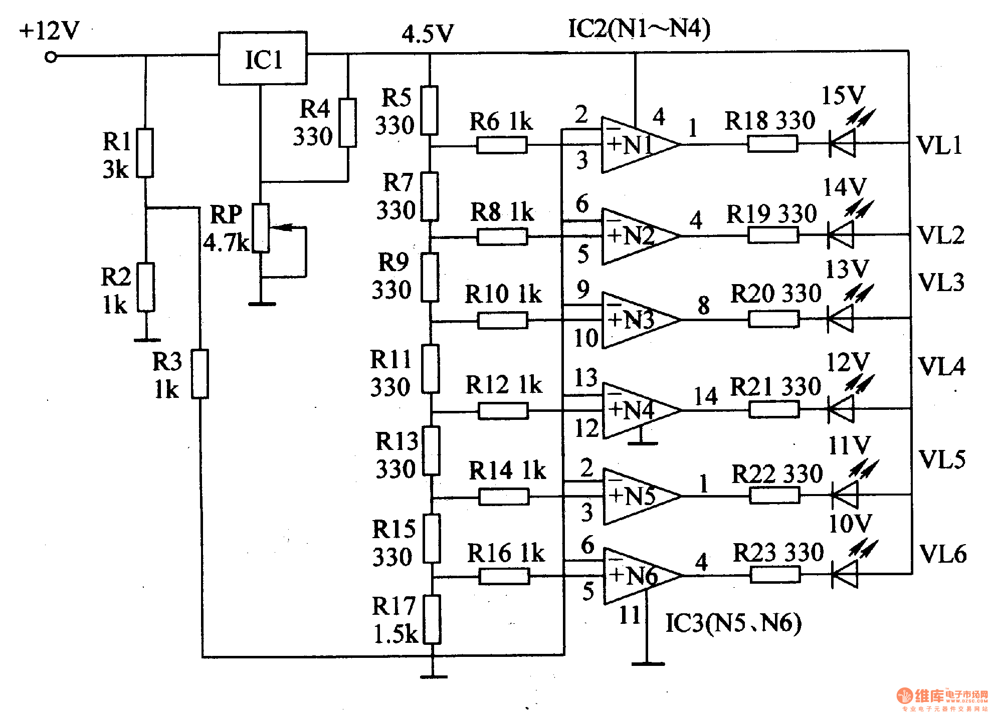
This document introduces an LED car voltmeter constructed using the op-amp LM312 and LED components. It is designed to display six voltage levels ranging from 10V to 15V, with each level representing a 1V increment. The working principle of...
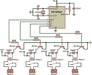
This is a relay driver based on a PIC16F84A microcontroller. The board includes four relays, allowing control of four distinct outputs. The relay driver circuit utilizing the PIC16F84A microcontroller is designed for controlling multiple devices or systems through relay activation....
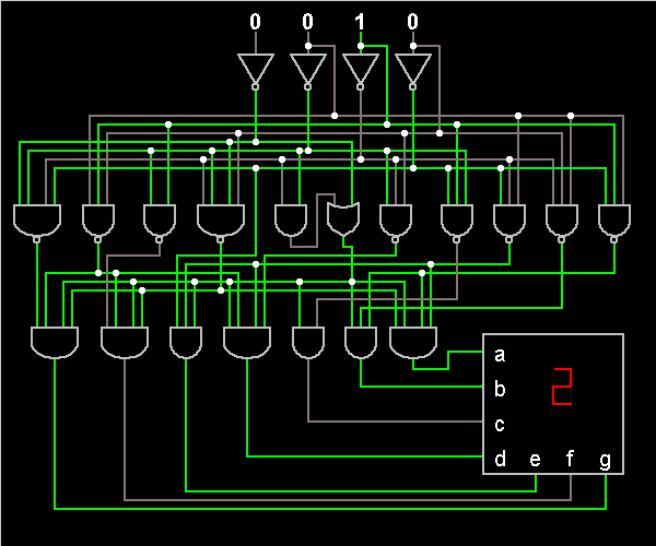
It is possible to implement a circuit using both P-MOS and N-MOS transistors, referred to as CMOS technology. In this context, a three-terminal NAND gate can be constructed. This gate is classified as a universal gate, widely utilized in...
Common emitter amplifier circuit with resistance and capacitance coupling. The common emitter amplifier circuit is a fundamental configuration in analog electronics, widely utilized for its ability to amplify voltage signals. This circuit employs a bipolar junction transistor (BJT) as the...
The schematic presented is a circuit for a 555 tracking transmitter. The 555 timer is a well-known versatile integrated circuit utilized in various electronic projects. In the circuit described, this IC generates a tone that is transmitted through an...

This dimming-controlled LED driver electronic circuit requires an input voltage of 36 volts and will provide an output voltage of 24 volts at a maximum current of 700 mA. The described dimming-controlled LED driver circuit is designed to efficiently convert...