
PIC16F84A Controlled Relay Driver
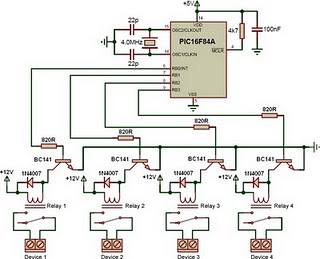
The relay driver circuit utilizing the PIC16F84A microcontroller is designed for controlling multiple devices or systems through relay activation. The PIC16F84A is an 8-bit microcontroller featuring 13-bit instruction architecture and a 14-bit program memory. It is well-suited for applications requiring logic control and output interfacing.
In this schematic, the microcontroller interfaces directly with four relays, which are typically electromechanical switches. Each relay is connected to a specific output pin of the microcontroller, allowing for individual control. The relays are powered through a suitable power supply, ensuring that the voltage and current ratings meet the requirements of the devices being controlled.
To drive the relays, the circuit incorporates transistor drivers. Each output pin from the PIC16F84A connects to the base of a transistor through a current-limiting resistor. When the microcontroller sends a high signal to the transistor, it allows current to flow from the collector to the emitter, energizing the relay coil. A flyback diode is placed in parallel with the relay coil to protect the circuit from voltage spikes generated when the relay is de-energized.
The design may also include additional components such as pull-down resistors to ensure stable operation of the microcontroller inputs and capacitors for filtering power supply noise. The board layout should be optimized for minimizing interference and ensuring reliable operation, particularly if the relays are controlling inductive loads.
Programming the PIC16F84A involves writing firmware that defines how the microcontroller responds to inputs, manages timing for relay activation, and ensures safe operation of the connected devices. The firmware should also include debounce logic if mechanical switches are used as inputs to prevent false triggering of relays.
This relay driver circuit is applicable in various automation projects, including home automation, industrial control systems, and remote device management, providing a robust solution for controlling multiple outputs efficiently.This is a relay driver that is based on a PIC16F84A microcontroller. The board includes four relays so this lets us to control four distinct .. 🔗 External reference
Related Circuits
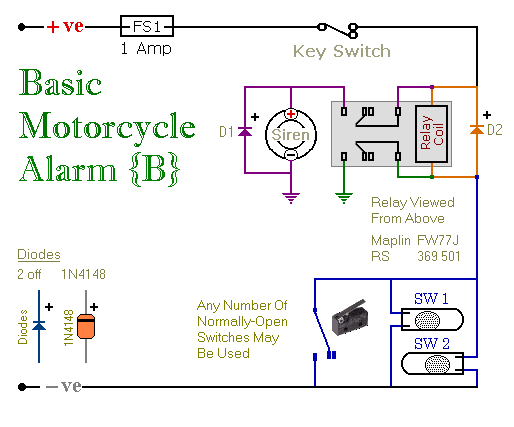
These are two easy-to-build relay-based alarms. They can be used to protect a motorcycle, but they have many additional applications. When using relays with 6-volt coils, they can safeguard a classic bike. Both alarms are compact, with completed boards...

The HS-3182 is a monolithic dielectrically isolated bipolar differential line driver designed to meet the specifications of ARINC 429. This device is intended to be used with a companion chip, the HS-3282 CMOS ARINC Bus Interface Circuit, which provides...

This is a relay circuit that detects the presence of sound to activate the relay. This sound-controlled relay can be utilized as a voice-operated switch or for controlling lights. The sound-activated relay circuit typically employs a microphone or a sound...
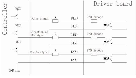
Connection of a drive and a two-phase hybrid stepper motor using a four-wire system, with the motor windings configured in both parallel and series connections. This method allows for high-speed performance, although it requires a large drive current (1.73...
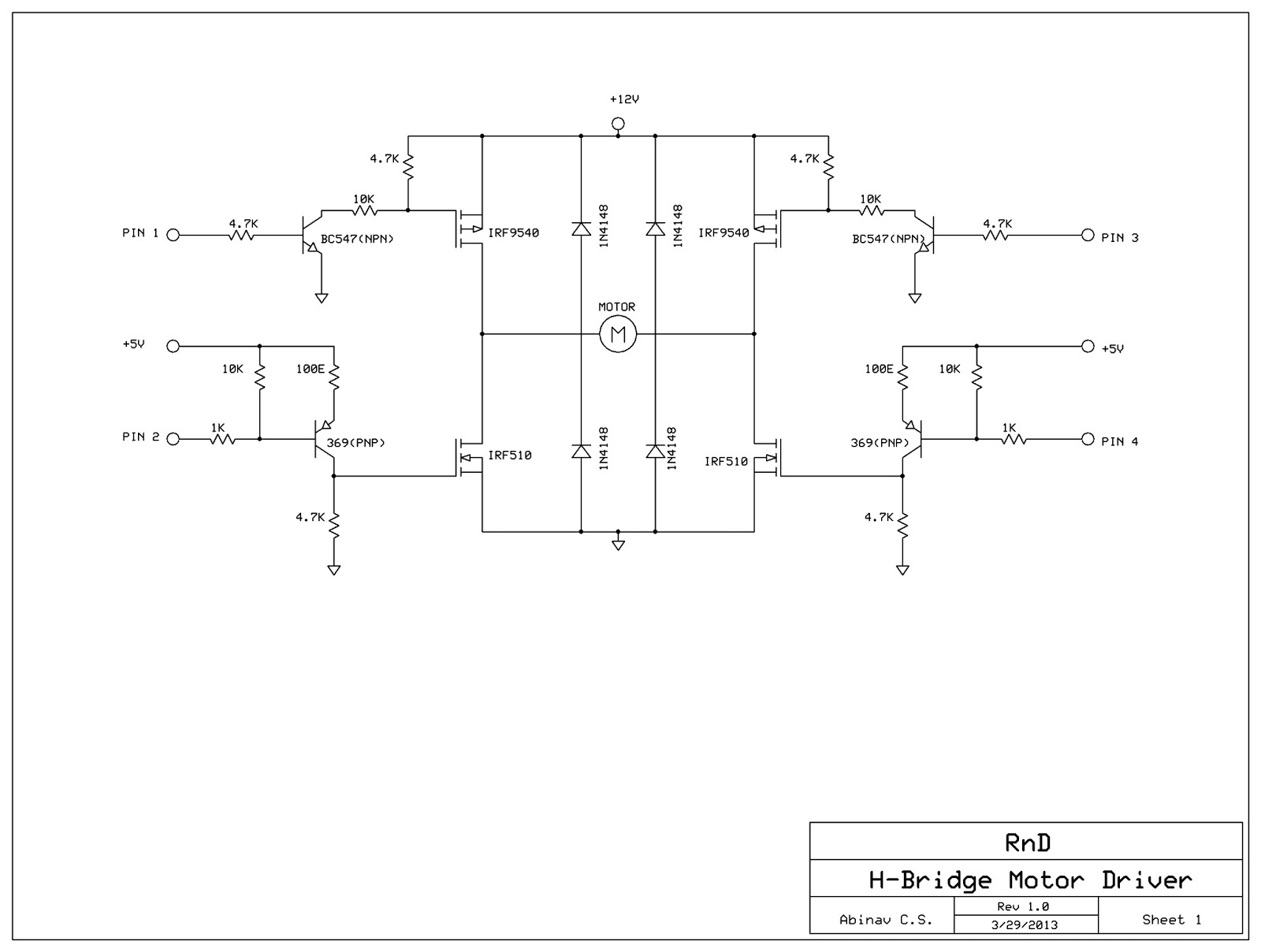
This post discusses the construction of an H-Bridge Motor Driver circuit using simple MOSFETs and transistors. The primary feature of this H-Bridge is its ability to drive a motor in both directions. An H-Bridge is a circuit that allows...
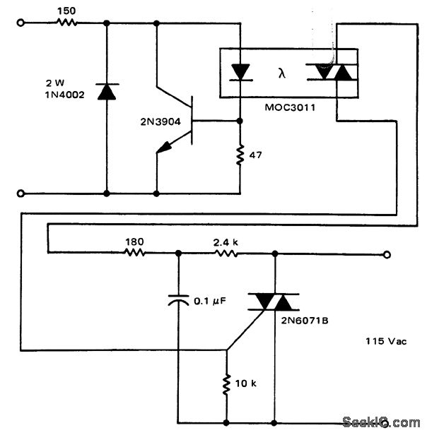
A solid-state relay circuit features an input protection mechanism utilizing the MOC3011 triac driver. The input voltage for the protection circuit can range from 3 to 30 volts DC, as noted by Motorola Semiconductor Products Inc. The solid-state relay (SSR)...