
555 logic test circuit diagram pen
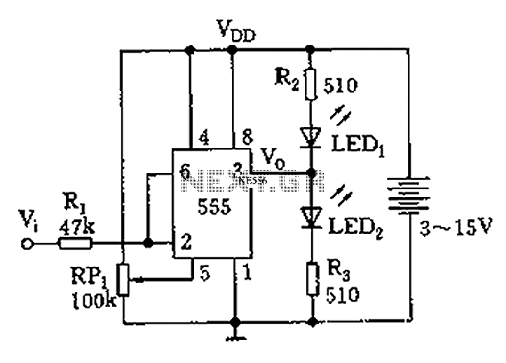
The circuit primarily utilizes a 555 timer IC configured in a monostable or astable mode, depending on the desired application. The Schmitt trigger feature provides hysteresis, which is critical for distinguishing between high and low logic levels in noisy environments. The input signal is connected to pin 2 (trigger) of the 555 timer, while pin 6 (threshold) is used to determine the switching points for the LEDs.
LED1 and LED2 serve as visual indicators of the logic state. The adjustment potentiometer (RP1) allows for fine-tuning the reference voltage at pin 5, which is essential for accurate testing of digital circuits. The resistor values and capacitor connected to the 555 timer are selected to ensure that the timing characteristics suit the application, providing stable operation across a range of input conditions.
In the context of testing a -24V PMOS circuit, the circuit is designed to withstand higher input voltages, ensuring that the 555 timer operates correctly without damage. The output states of the LEDs provide immediate feedback on the logic level, which is crucial for troubleshooting and verifying the functionality of digital components. This circuit can be an invaluable tool for engineers and technicians working with digital electronics, allowing for quick assessments of circuit performance and integrity. As shown in Figure 555 is a simple logic circuit test leads. Test pen 555 as the core, it will take a Schmitt trigger, the logic state of the test for digital circuit. 2,6 555 feet and then, when the input signal level is 0, 555 set, LED2 light; when the input is 1, LED1 lights. For example, when Vdd 4.5V, the measurement TTL circuit, adjust RP1, so 5 feet potential 2.4V, the Schmitt trigger R end (6 feet) trigger level 2.4V, S end (2 feet ) level is 1.2V.
When the input level is higher than 2.4V, LED1 lights; below 1.2V, LED2 light. This circuit is used to test the operating voltage of -24V PMOS circuit.
Related Circuits
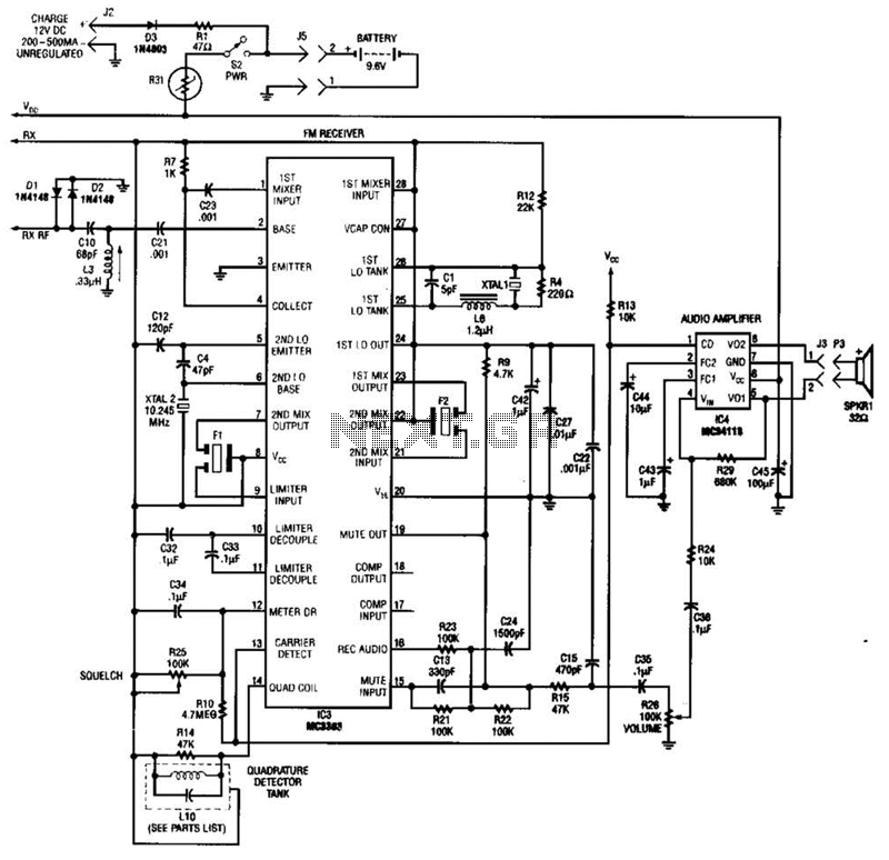
Using a Motorola MC3363 LSI one-chip FM receiver, the circuit is a dual-conversion FM receiver with a 10.7-MHz IF chain. IC4 provides power to drive a small speaker. The described circuit employs the Motorola MC3363 integrated circuit, which is designed...
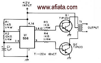
The first section of the 555 timer is configured as an astable oscillator, with R2 and C1 determining the frequency. The output is accessible at pin 5. The second section functions as a phase inverter, with its output available...

By adjusting one potentiometer, the output of this circuit can be varied from a positive version of the input signal, smoothly transitioning through zero output, and then to a negative version of the input. For instance, if the input...
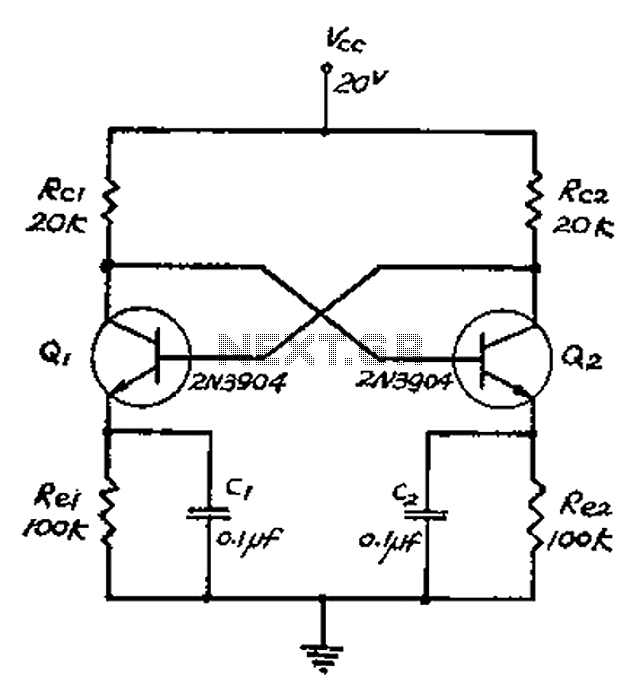
The collector and base-emitter bias of the transistor are directly coupled to each other. Each transmitter circuit controls the capacity conversion function. The emitter generates a triangular wave. The two transistors are not continuously in an active state. Instead,...

Figure 4-7 illustrates the pitch analysis based on the relationship derived from the design calculation of the control circuit. In this setup, Ai serves as a buffer for the large stage, thereby alleviating the load on the preamplifier output....
The name of our game, LED Zeppelin, is a play on words. It comes not from the pop group of the same name but from Graf Von Zeppelin, a German who invented the first rigid air ship in 1900....