
Polarity Gain Adjustment Circuit
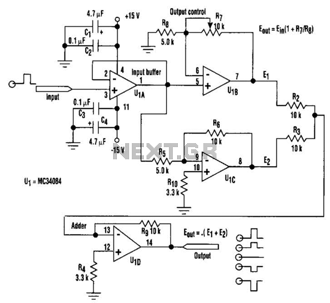
The described circuit utilizes a quad operational amplifier configuration, which allows for versatile signal manipulation. The input buffer provided by the A section ensures that the input signal is isolated from the subsequent processing stages, preventing loading effects that could distort the signal. The fixed negative output of -4 V from op amp 0 serves as a reference point for the output variations, while the adjustable output from the other op amp allows for fine-tuning of the signal range.
The ability to vary the output from +2 V to +6 V peak enables a wide range of applications, particularly in audio and signal processing where phase and amplitude control are crucial. The D section's function of summing the outputs from the C and D sections facilitates the smooth transition of the output voltage, making it suitable for applications requiring precise control over the output signal's amplitude and phase.
In practical applications, this circuit can be employed in audio systems to create effects such as amplitude modulation or dynamic range compression, where the output signal needs to be carefully adjusted in relation to the input. Additionally, the capability to switch the phase of the output signal makes this circuit useful in applications such as phase-sensitive detection, where the relationship between input and output phases is critical for signal integrity and processing accuracy. Overall, this circuit exemplifies a flexible and effective approach to signal modulation using operational amplifiers. By adjusting one potentiometer, this circuit`s output can be varied from a positive-going version of the input signal, smoothly through zero output, then to a negative-going version of the input (see the figure). If the input signal is a positive pulse of, for example, +2-V peak/the output pulse amplitude can be smoothly varied from +2-V through ground (no output) to a -2-V peak.
Taking a closer look at the setup, assume that the signal has a +2-V peak input. The A section of the quad op amp is an input buffer, op amp 0 provides a fixed negative-going output of -4-V peak, and op amp supplies a positive-going output that varies from +2-V to +6-V peak. The D section adds the and C outputs. Thus, by varying the output, the circuit output varies smoothly from -2-V to +2-V peak. The circuit can, of course, also be used as a 07180 phase switcher. For instance, with a ground-centered sine-wave input of 4V p-p, the output varies from 4-V p-p in phase with the input, smoothly through 0 V, to 4V p-p 180 out of phase with the input. 🔗 External reference
Related Circuits
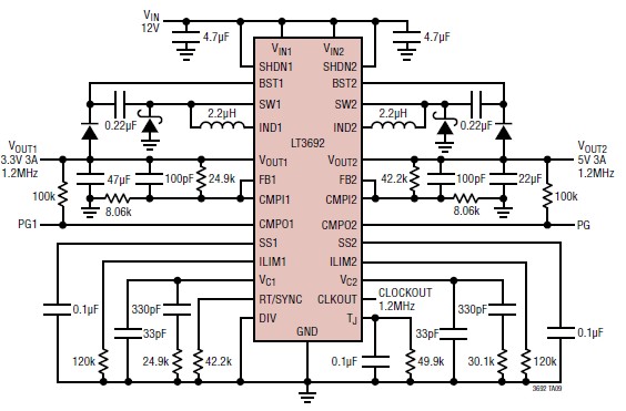
The LT3692 dual current mode PWM step-down DC-DC converter circuit, featuring two internal 3.5A switches, can be designed into a simple power supply circuit suitable for various electronic applications, such as distributed supply regulation or automotive circuits. The LT3692...
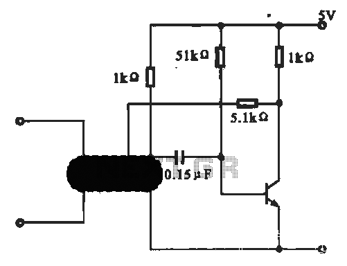
This circuit illustrates an oscillator that is controlled by an optocoupler, utilizing photoelectric coupling to drive a transistor. The oscillator circuit described operates by employing an optocoupler to provide electrical isolation between its input and output stages while allowing control...
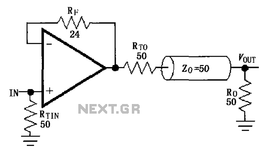
The MAX4450/4451 unity gain line is illustrated in the driving circuit. The MAX4450/4451 features internal compensation, a 24-ohm resistor in series within a feedback loop, along with capacitors and inductors that can reduce the Q value of the feedback...
The FM demodulator circuit, as illustrated in the figure, utilizes a 4046 Phase-Locked Loop (PLL) integrated circuit to convert the intermediate frequency FM input signal into a lower frequency output. The FM demodulator circuit based on the 4046 PLL IC...
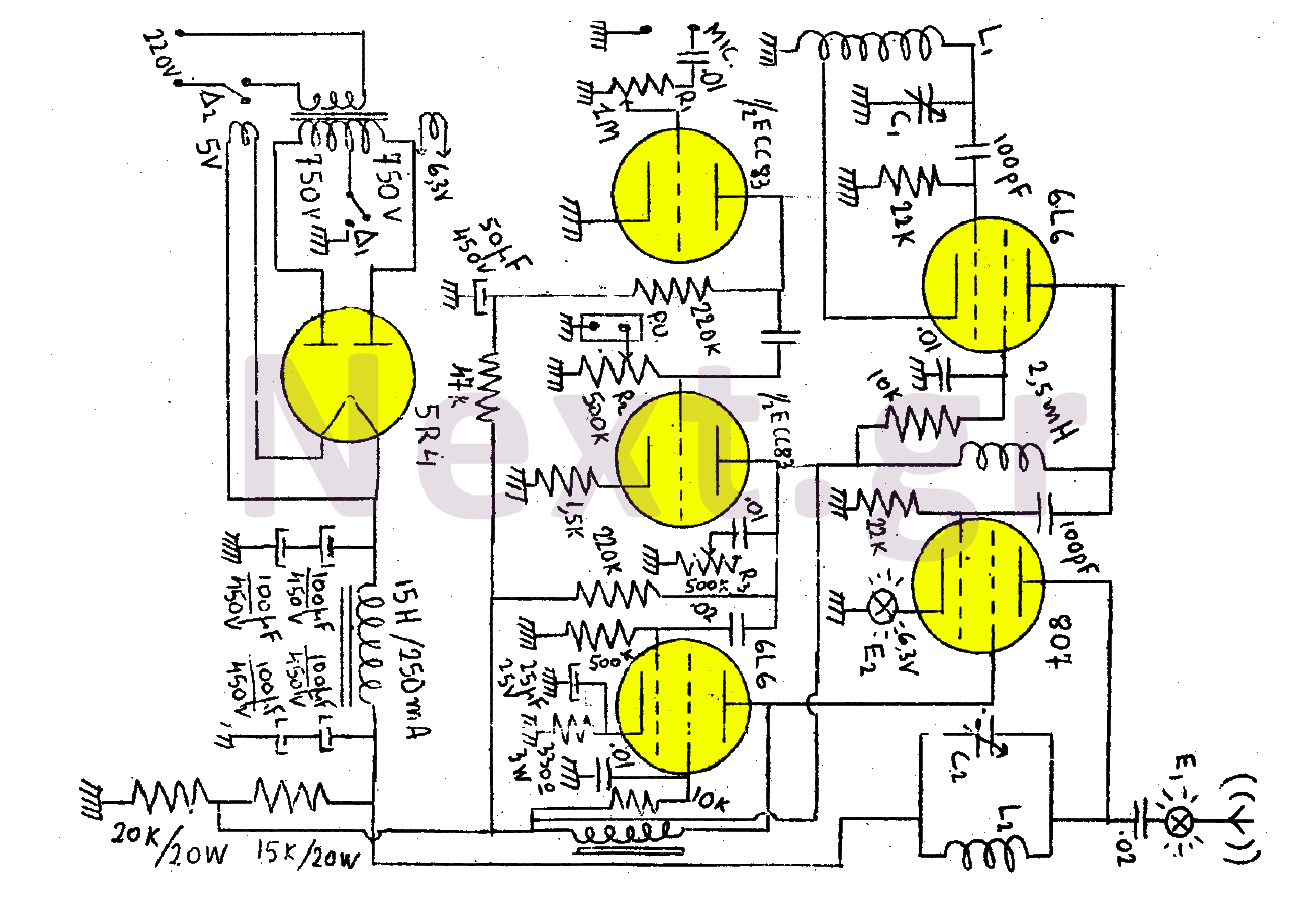
This transmitter consists of a total of five bulbs. The 6L6 tube functions as an oscillator, directing oscillations to the grid of the 807 tube, which serves as the final amplifier and the transmitter output lamp. The amplifier includes...
Color sensing using a camera and a sufficiently powered processor that runs image histogram logic (or similar algorithms) can reliably determine the presence of specific colors. However, alternatives that are significantly more cost-effective for detecting the presence or absence...
Warning: include(partials/cookie-banner.php): Failed to open stream: Permission denied in /var/www/html/nextgr/view-circuit.php on line 713
Warning: include(): Failed opening 'partials/cookie-banner.php' for inclusion (include_path='.:/usr/share/php') in /var/www/html/nextgr/view-circuit.php on line 713