
555 square wave generator
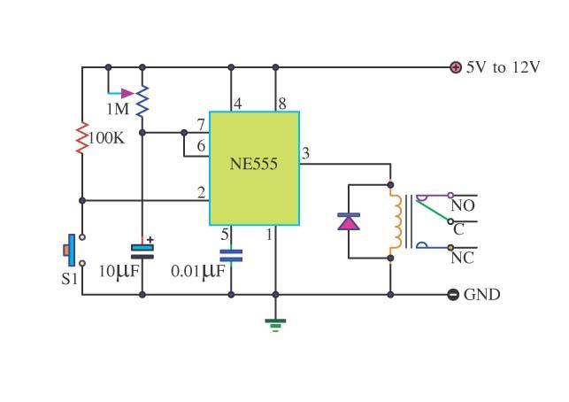
The square wave generator circuit typically consists of a few key components: a timer IC, such as the 555 timer, resistors, capacitors, and possibly a diode for protection. The 555 timer can be configured in astable mode to produce a continuous square wave output. This output is characterized by its alternating high and low voltage levels, which can be adjusted by changing the values of the resistors and capacitors in the circuit.
In an astable configuration, the 555 timer oscillates between its high and low states, generating a square wave signal. The frequency of the output waveform is determined by the formula:
\[ f = \frac{1.44}{(R1 + 2R2)C} \]
where \( R1 \) and \( R2 \) are the resistances connected to the timer, and \( C \) is the capacitance of the timing capacitor. By selecting appropriate values for \( R1 \), \( R2 \), and \( C \), the desired frequency for the speedometer can be achieved.
The output from the 555 timer can then be connected to the speedometer circuit board. This output may require buffering if the load is significant or if the input of the speedometer circuit cannot handle the output directly. A transistor can be used to amplify the signal if necessary.
Additionally, it is important to ensure that the power supply voltage levels are compatible with both the 555 timer and the speedometer circuit to prevent damage. Proper decoupling capacitors should also be included near the power pins of the 555 timer to ensure stable operation.
In summary, the square wave generator serves as a fundamental building block for driving the speedometer circuit, providing a reliable and adjustable frequency output necessary for accurate speed measurement.Hello, Please help me, I have designed a very basic square wave generator to run a speedometer circuit board which is providing output to control a.. 🔗 External reference
Related Circuits
The Simple Timer with a 555 timer is a basic timer circuit that can be utilized in various electronic devices. This circuit leverages the monostable multivibrator mode of the 555 Integrated Circuit (IC). The output control circuit is designed...

The remote control circuit consists of two main components: the transmitter and the receiver. A simple schematic diagram illustrates the remote control setup. The transmitter circuit utilizes a NE555 timer IC to generate a specific frequency. The receiver circuit...
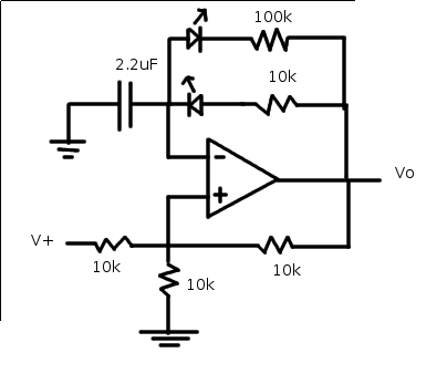
The relaxation oscillator generates a relatively consistent square wave. By altering the duty cycle, the effect can be visualized using LEDs. The following variation of the relaxation oscillator circuit can be assembled. The relaxation oscillator circuit typically consists of a...
This circuit is intended to let the user turn off a lamp by means of a switch placed far from bed, allowing him enough time to lie down before the lamp really switches off. 15 seconds delayed switch-off. A...
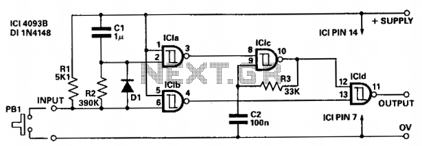
The circuit provides independent control of the initial delay and pulse rate. ICIc functions as a pulse generator, with its operation inhibited by the normally low output of ICla. When the circuit input transitions to low (e.g., when pressing...
The 8-pin 555 timer is one of the most versatile integrated circuits (ICs) available, utilized in numerous projects. With minimal external components, it can be employed to construct various circuits, many of which do not pertain to timing applications....