
pulse generator circuit
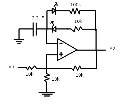
The relaxation oscillator circuit typically consists of a resistor, capacitor, and a transistor or operational amplifier configured to produce a square wave output. In this variation, the duty cycle can be modified by adjusting the resistance and capacitance values, which influences the charging and discharging time of the capacitor.
To visualize the changes in duty cycle, LEDs can be incorporated into the circuit. When the output switches states, the LEDs will illuminate, providing a clear indication of the oscillation frequency and duty cycle. The circuit can be designed using a 555 timer IC in astable mode, where the duty cycle is determined by the ratio of the resistances and capacitance used in the timing configuration.
By selecting different resistor values (R1 and R2) and a capacitor (C1), the frequency and duty cycle can be manipulated. The duty cycle can be calculated using the formula:
Duty Cycle (%) = (R1 + R2) / (R1 + 2R2) * 100
This allows for precise control over the output waveform characteristics. The circuit should be powered by a suitable DC voltage source, and the output can be taken from the discharge pin of the 555 timer.
The schematic should indicate the connections for the resistors, capacitor, and the LED, ensuring that the LED is placed in series with a current-limiting resistor to prevent excessive current flow. By observing the LED's brightness and on/off timing, the effects of varying the duty cycle can be effectively demonstrated.With the relaxation oscillator, we basically achieved a fairly regular square wave. Let's change the duty cycle (and visualize the effect with LEDs). Wire up the following variation on the relaxation oscillator circuit 🔗 External reference
Related Circuits
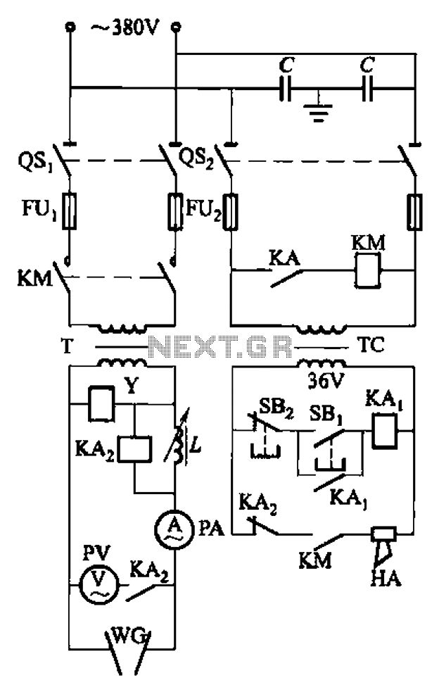
The GH-75 type circuit is a hydrogen atom welder that utilizes hydrogen bonding without melting the workpiece. This process involves the use of a tungsten electrode to generate an electric arc, which effectively welds the workpiece in a hydrogen-protected...
Hobby servos convert DMX signals into mechanical motion. Typically, hobby servos require a pulse with a variable width ranging from 1 to 2 milliseconds, with 1.5 milliseconds representing the center position. The schematic below illustrates a simple voltage-to-pulse-width circuit....
This device is a combination digital clock timer and solar panel charge controller designed to maintain a deep cycle battery from a solar panel. The timer output controls a 12-volt load for a 32-minute interval each day. The start...
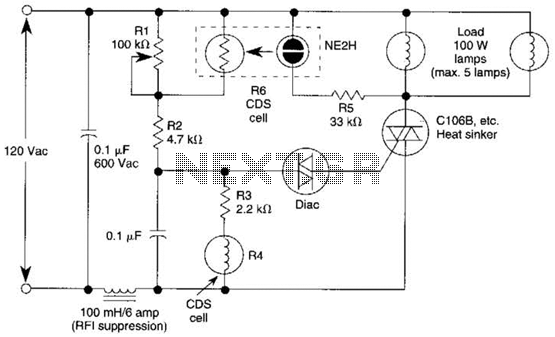
A neon bulb and a CdS photocell are enclosed in a light-tight enclosure to form an optocoupler. A diac/triac combination is employed to create a snap-switch effect. A second CdS photocell serves as the primary sensor. As darkness approaches,...
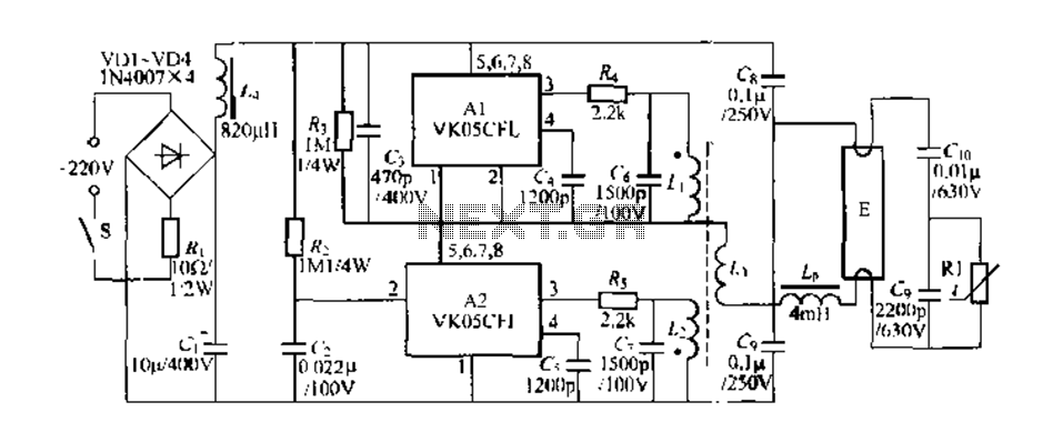
Figure 289 illustrates the VK05CIl, an ASIC produced by STMicroelectronics (ST) designed to operate low-power compact fluorescent lamps ranging from 5 to 15W. The VK05CFI is engineered to drive approximately 23W low-power compact fluorescent lamps using high-pressure composite bipolar...

This motion detector alarm is capable of detecting a moving person from a distance of 1 meter. It utilizes a dual IR Transmitter-Receiver module, specifically the HOA1405. The motion detector alarm system operates on the principle of infrared (IR) detection,...