
timer 555 schematic
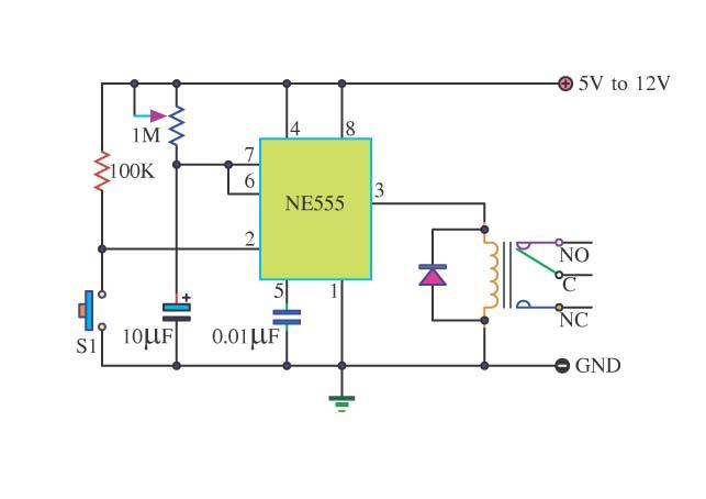
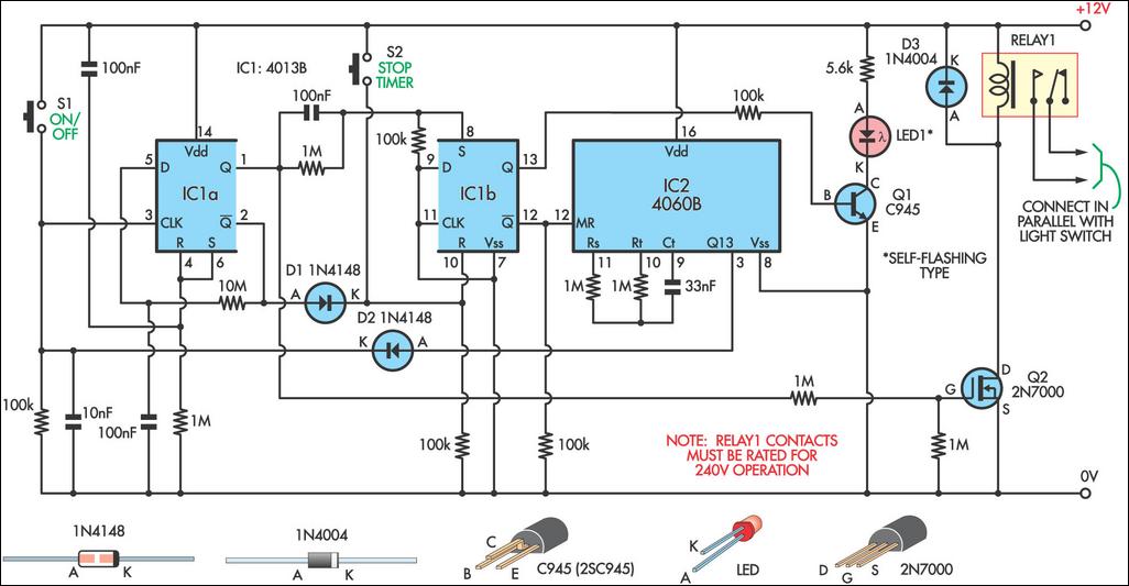
The Simple Timer circuit using the 555 timer is a versatile and straightforward design suitable for various applications, including automatic lighting systems, delay timers, and pulse generation. The 555 timer operates in monostable mode, meaning it outputs a single pulse when triggered. Upon pressing switch S1, the circuit transitions to its active state, and the timing begins. The duration of the output pulse is controlled by the RC time constant, which is a product of the resistance (R) and capacitance (C) values in the circuit.
In this configuration, the variable resistor (VR1) allows for adjustable timing, enabling users to set the desired duration of the output pulse. The capacitor (C) stores charge and discharges through the resistor, determining how long the output remains active. The choice of components is crucial for achieving precise timing; thus, using a tantalum capacitor, known for its stability and low leakage current, alongside a high-quality resistor, ensures minimal deviation from the expected timing.
The relay output can handle AC loads, making this circuit applicable for switching devices such as lamps or motors. The selection between normally closed and normally open connections allows for flexibility in design, depending on whether the load should be activated or deactivated upon triggering the timer. The circuit can be powered by a DC supply within the specified voltage range, making it adaptable for various electronic projects. Overall, the Simple Timer circuit with a 555 timer is an effective solution for timing applications in both hobbyist and professional electronic designs.Simple Timer With 555 is one example of a simple timer and can be applied to electronic equipment. With 555 Timer Simple series takes advantage of the mode of the IC monostable multivibrator 555. With the relay output control circuit can be used to control equipment with AC voltage source. With 555 Timer Simple circuit can work with source voltage of 5 - 12VDC depending on the relay used. In order to use Simple Timer With this 555 can be started by pressing the switch S1 to start the process of timing. In the relay there are 2 options that is normaly Close connection (NC) and normaly open (NO). The duration of the timing circuit 555 Simple Timer With RC configuration is determined by the VR 1 MOhm and C 10uF.
Active timer duration can be calculated with the formula T = 1. 1 RC where T (seconds), R (Ohm) and C (farad). To get more accurate results R and C components referred to in the formula should use good quality components, namely C of tantalum material and R with the quality of 1%. 🔗 External reference
Related Circuits
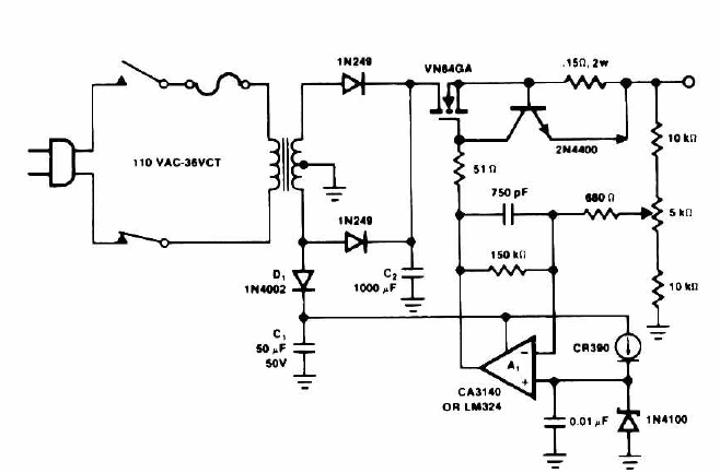
This circuit outputs a voltage of 14 volts with a maximum current of 4A. It can be used for NiCad batteries and accumulators, both wet and dry types. However, the accumulator must be rated for 12 volts and have...
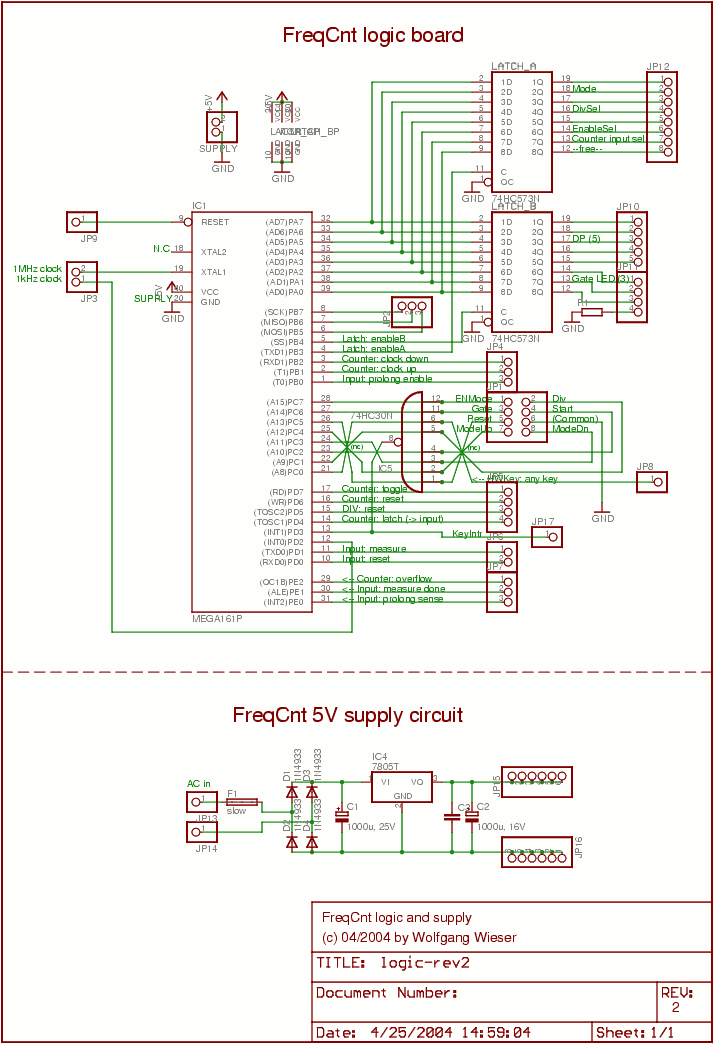
The lower schematic represents a standard bidirectional rectifier along with capacitors and a 7805 voltage regulator, which provides a stable 5V source to power the electronic components of the frequency counter. A fuse is included for security purposes. The...
The following circuit illustrates a Cat and Dog Repellent Timer Circuit Diagram. Features include a high-output ultrasonic transmitter and the use of a standard 555 timer. The Cat and Dog Repellent Timer Circuit is designed to emit high-frequency ultrasonic sound...
This 9-minute timer switch can be utilized to control lighting in a toilet or bathroom. The timer is activated by pressing switch S1 and deactivated by pressing S1 again. If the timer is not manually turned off, the light...
PowerMan UPS/Inverters manufactures uninterruptible power supplies and voltage regulators. The business was founded in 1993 and was involved in distribution prior to the year 2000. PowerMan specializes in providing reliable power solutions, including uninterruptible power supplies (UPS) and voltage regulators,...
This alarm circuit is based on two 555 timers. The alarm will sound your car horn if anyone opens the car door while the circuit is armed. The timers will allow you to leave the car without sounding the...
Warning: include(partials/cookie-banner.php): Failed to open stream: Permission denied in /var/www/html/nextgr/view-circuit.php on line 713
Warning: include(): Failed opening 'partials/cookie-banner.php' for inclusion (include_path='.:/usr/share/php') in /var/www/html/nextgr/view-circuit.php on line 713