
555 timer
The 555 timer IC is a versatile and widely utilized component in electronic circuits, serving various applications including timers, oscillators, and pulse-width modulation. Its internal architecture is designed to facilitate both monostable and astable operation modes. In monostable mode, the 555 timer generates a single output pulse in response to a triggering event, while in astable mode, it produces a continuous square wave output, with the frequency and duty cycle determined by external resistors and capacitors.
The standard pin configuration of the 555 timer includes pins for power supply, ground, trigger, threshold, discharge, output, reset, and control voltage. The trigger pin initiates the timing cycle, while the threshold pin detects when the capacitor voltage reaches a specific level to reset the timer. The discharge pin is connected to the timing capacitor, allowing it to discharge when the timing cycle completes. The output pin provides the timer's signal, which can drive various loads depending on the application.
In practical applications, the 555 timer can be employed in blinking LED circuits, tone generation, frequency modulation, and even simple motor control. Its resilience to voltage fluctuations and temperature variations makes it suitable for use in various environments. The ability to operate at different supply voltages and the availability of multiple package types further enhance its usability in diverse electronic projects. As a fundamental building block in electronics, the 555 timer continues to inspire innovation and creativity among engineers and hobbyists alike.The 555 timer IC was first introduced around 1971 by the Signetics Corporation as the SE555/NE555 and was called "The IC Time Machine" and was also the very first and only commercial timer ic available. It provided circuit designers and hobby tinkerers with a relatively cheap, stable, and user-friendly integrated circuit for both monostable and as
table applications. Since this device was first made commercially available, a myrad of novel and unique circuits have been developed and presented in several trade, professional, and hobby publications. The past ten years some manufacturers stopped making these timers because of competition or other reasons.
Yet other companies, like NTE (a subdivision of Philips) picked up where some left off. This primer is about this fantastic timer which is after 30 years still very popular and used in many schematics. Although these days the CMOS version of this IC, like the Motorola MC1455, is mostly used, the regular type is still available, however there have been many improvements and variations in the circuitry.
But all types are pin-for-pin plug compatible. Myself, every time I see this 555 timer used in advanced and high-tech electronic circuits, I`m amazed. It is just incredible. In this tutorial I will show you what exactly the 555 timer is and how to properly use it by itself or in combination with other solid state devices without the requirement of an engineering degree.
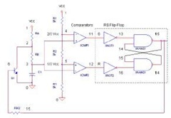
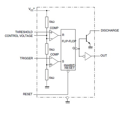
This timer uses a maze of transistors, diodes and resistors and for this complex reason I will use a more simplified (but accurate) block diagram to explain the internal organizations of the 555. So, lets start slowly and build it up from there. The 555, in fig. 1 and fig. 2 above, come in two packages, either the round metal-can called the `T` package or the more familiar 8-pin DIP `V` package.
About 20-years ago the metal-can type was pretty much the standard (SE/NE types). The 556 timer is a dual 555 version and comes in a 14-pin DIP package, the 558 is a quad version with four 555`s also in a 14 pin DIP case. I nside the 555 timer, at fig. 3, are the equivalent of over 20 transistors, 15 resistors, and 2 diodes, depending of the manufacturer.
The equivalent circuit, in block diagram, providing the functions of control, triggering, level sensing or comparison, discharge, and power output. Some of the more attractive features of the 555 timer are: Supply voltage between 4. 5 and 18 volt, supply current 3 to 6 mA, and a Rise/Fall time of 100 nSec. It can also withstand quite a bit of abuse. The supply current, when the output is `high`, is typically 1 milli-amp (mA) or less. The initial monostable timing accuracy is typically within 1% of its calculated value, and exhibits negligible (0.
1%/V) drift with supply voltage. Thus longterm supply variations can be ignored, and the temperature variation is only 50ppm/ °C (0. 005%/ °C). All IC timers rely upon an external capacitor to determine the off-on time intervals of the output pulses. As you recall from your study of basic electronics, it takes a finite period of time for a capacitor (C) to charge or discharge through a resistor (R).
Those times are clearly defined and can be calculated given the values of resistance and capacitance. The basic RC charging circuit is shown in fig. 4. Assume that the capacitor is initially discharged. When the switch is closed, the capacitor begins to charge through the resistor. The voltage across the capacitor rises from zero up to the value of the applied DC voltage. The charge curve for the circuit is shown in fig. 6. The time that it takes for the capacitor to charge to 63. 7% of the applied voltage is known as the time constant (t). That time can be calculated with the simple expression: Assume further that the applied voltage is 6 volts.
That means that it will take one time constant for the voltage across the capacitor to reach 63. 2% of the applied voltage. Theref 🔗 External reference
Related Circuits
The 555 Timer IC operates in three modes: monostable, astable, and bistable/Schmitt trigger. This article will focus on its astable mode. The astable mode of the 555 Timer IC is characterized by its ability to generate a continuous square wave...
The following circuit is a basic 555 square wave oscillator. Features include a 1 kHz tone, simple circuitry, a current limit of 200 mA, reduced inductive voltage, and a supply voltage range of 4.5 to 9 volts. Components used...
A square wave oscillator utilizing the 555 integrated circuit (IC) can be configured to produce symmetric oscillation with a 50% duty cycle. Additional circuit configurations employ diodes to separate the charging and discharging paths. The 555 timer IC is a...
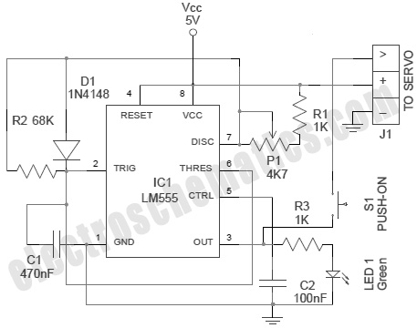
A servo is an error-sensing feedback control mechanism used to correct the performance of a system. A servo motor is a DC motor equipped with a servo mechanism. A servo motor is an electromechanical device that utilizes a closed-loop control...
This device is a simple timer that keeps the headlights of a vehicle illuminated for approximately 1 minute and 30 seconds. This feature is particularly useful when accessing dark areas, eliminating the need to return to manually switch off...
A low power H-bridge may be necessary for driving a motor. The 555 integrated circuit (IC) can handle a load of up to 200 mA, either sourcing or sinking, making it a potential driver if the output can be...
Warning: include(partials/cookie-banner.php): Failed to open stream: Permission denied in /var/www/html/nextgr/view-circuit.php on line 713
Warning: include(): Failed opening 'partials/cookie-banner.php' for inclusion (include_path='.:/usr/share/php') in /var/www/html/nextgr/view-circuit.php on line 713