
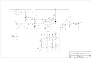
Basic 555 Squarewave Oscillator circuit
The 555 timer integrated circuit (IC) operates in astable mode to generate a square wave output, which can be used to drive a speaker and produce sound. The circuit is designed to oscillate at a frequency of approximately 1 kHz, which is suitable for generating audible tones. The frequency of oscillation is primarily determined by the resistor and capacitor values connected to the 555 timer.
In this configuration, two resistors (R1 and R2) and a capacitor (C1) are connected to the 555 timer. The values of R1 and R2 set the charge and discharge times of the capacitor, thus establishing the frequency of the output waveform. The relationship between the resistor and capacitor values can be expressed using the formula for frequency in astable mode:
\[ f = \frac{1.44}{(R1 + 2R2) \cdot C1} \]
To achieve the desired frequency of 1 kHz, appropriate values for R1, R2, and C1 must be selected.
The output from the 555 timer is fed into the base of a 2N3053 transistor, which acts as a switch. When the 555 timer outputs a high signal, the transistor is turned on, allowing current to flow through the speaker, producing sound. A push button can be integrated into the circuit to control the operation of the oscillator, allowing the user to start or stop the sound output.
The circuit is designed to operate within a supply voltage range of 4.5 to 9 volts, making it versatile for various applications. The current limit of 200 mA ensures that the circuit remains safe and prevents damage to components, particularly when driving inductive loads. Additionally, measures are taken to reduce inductive voltage spikes that could potentially harm the circuit, enhancing its reliability.
Overall, this basic 555 square wave oscillator circuit is an excellent example of simple and effective electronic design, suitable for educational purposes or as a building block for more complex audio applications.The following circuit is a Basic 555 squarewave oscillator. Feature : 1 Khz tone, Simple circuitry, limit = 200 mA, inductive voltage reduced, 4.5-9 Supply voltage. Component : 555 timer IC, resistor, capacitor, Speaker, 2N3053 transistor, push button. 🔗 External reference
Related Circuits
This audio-video circuit enables wireless audio and visual transmission to a television. The television functions as a receiver, eliminating the necessity for a separate monitor. It can also be connected to a VCR or CCD camera, and can be...
Very little extra circuitry is needed to do both forward and backward walking sequences along with a few other tricks. The PIC16F818 has a lot of features that work well in this situation. As you can see from the...
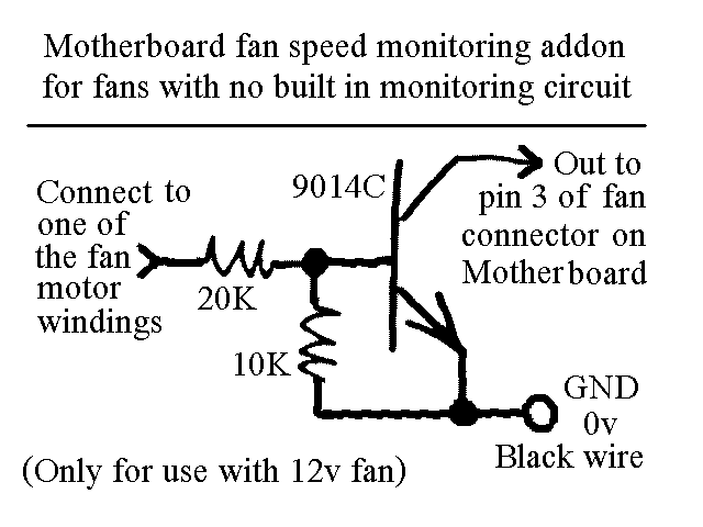
You will find this identical circuit inside most 3 wire computer fans with speed monitoring output to the motherboard. Peel off the sticker from the fan hub in order to access a motor winding pin for connecting up the...
The operating voltage for capacitors C1 and C2 should be raised to 25V if a 12V energy source is used. A general guideline is that the operating voltage of capacitors should be at least double the supplied voltage; for...
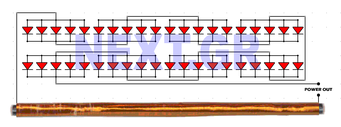
This schematic converts surrounding radio waves into usable electrical current. The power levels can be increased by incorporating additional diodes. The key factors in this device are the type of diodes used and the construction of the antenna. The...
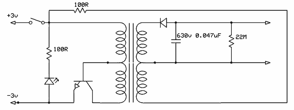
Free energy motors and generators are available for purchase, featuring plans for overunity devices. These devices resemble oscillators used in Joule thief circuits, although there may be some errors present in the designs. However, the concept remains clear. Free energy...