
555 Timer IC For IR Detector Circuit
The 555 Timer IC is a versatile device commonly utilized in various timing, pulse generation, and oscillator applications. In the context of an IR detector circuit, the 555 Timer can be configured in either monostable or astable mode, depending on the specific requirements of the application.
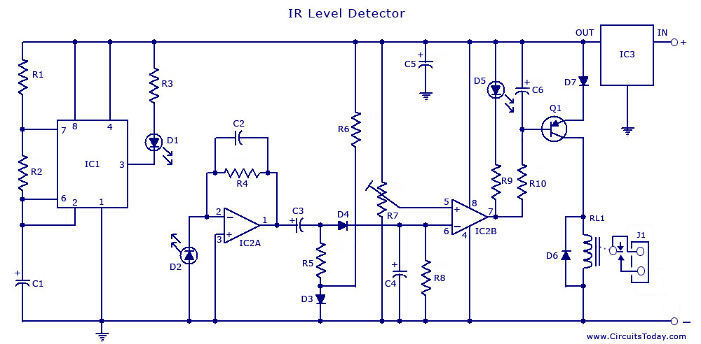
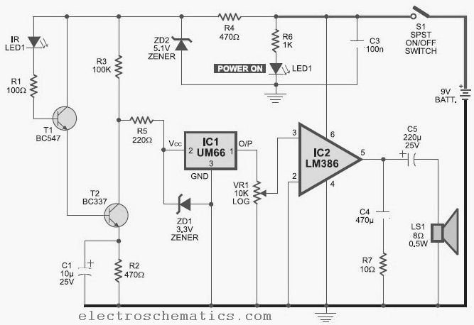
In this particular configuration, the circuit operates in astable mode, generating a continuous square wave output. The duty cycle of 0.8 milliseconds indicates the time duration the output remains high during each cycle, while the frequency of 120 Hz determines how often the cycle repeats per second. The peak current of 300 mA indicates the maximum current the circuit can supply to drive connected components, such as IR LEDs or phototransistors.
The circuit typically includes a few essential components: resistors, capacitors, and the 555 Timer IC itself. The resistors set the timing intervals, while the capacitor determines the charge and discharge times, which ultimately influence the frequency and duty cycle of the output signal.
When designing an IR detector, careful consideration must be given to the selection of these components to ensure the desired performance characteristics. The output from the 555 Timer can be used to drive an IR LED, which emits infrared light. This light can be reflected by nearby objects and detected by a phototransistor or photodiode, allowing the circuit to respond to the presence or absence of objects in its vicinity.
Overall, the 555 Timer IC provides a reliable and efficient solution for creating an IR detector circuit, with the specified parameters allowing for effective detection capabilities in various applications.The following circuit shows about 555 Timer IC For IR Detector Circuit. Features: duty cycle of 0.8mSec, frequency of 120Hz and 300 mA peak .. 🔗 External reference
Related Circuits
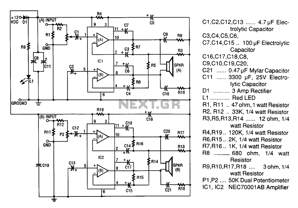
A 20W + 20W stereo amplifier comprises two independent 20-watt RMS amplifiers configured in a bridge arrangement. The input source is connected to a shunt voltage amplifier through resistors R1, R2, and potentiometer P1. Resistor R1 provides load resistance...

This circuit is designed to convert continuously lit lamps into flashing lights. It can be easily integrated into an existing circuit by inserting it between the lamp and the negative supply. It is particularly suitable for use with car...
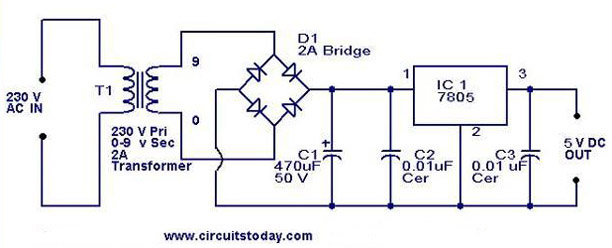
A 5V power supply using IC 7805 is designed and explained with a neat circuit diagram. The circuit for a 5V power supply utilizing the IC 7805 voltage regulator is a straightforward and efficient design that provides a stable output...
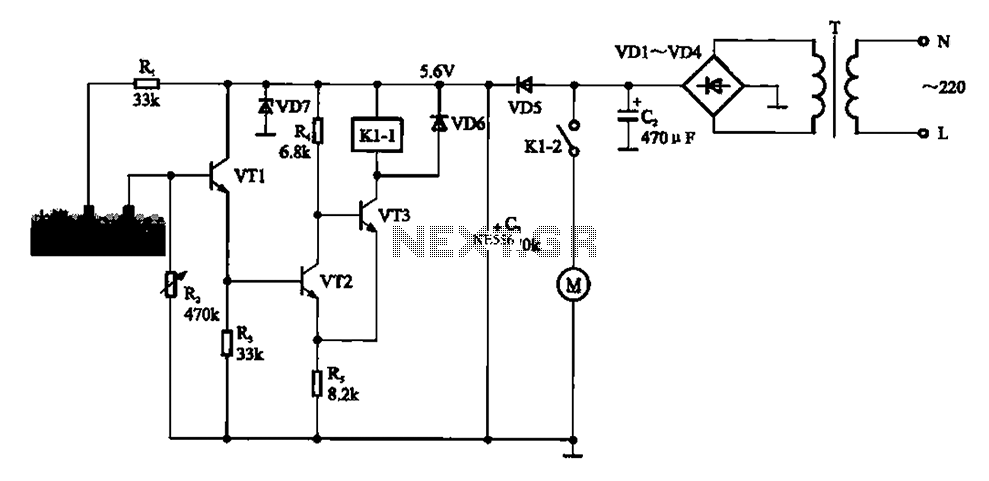
Automatic sprinkler control circuit. This circuit primarily consists of a humidity sensor, a detection signal amplifying circuit (including transistors VT1, VT2, and VT3), a power supply circuit (comprising a filter capacitor C2, a bridge conditioning circuit UR, and a...
This infrared detector is capable of detecting the presence of modulated infrared signals in its vicinity from various electronic sources, such as an IR handheld remote. The infrared detector operates by utilizing a photodetector that is sensitive to infrared light....
Cuckoo Sound Generator Circuit Schematic. This circuit generates a two-tone effect similar to the cuckoo song. It can be utilized for doorbells or other applications due to a built-in audio amplifier and loudspeaker. The Cuckoo Sound Generator Circuit is designed...