
Automatic sprinkler control circuit
The automatic sprinkler control circuit is designed to enhance the efficiency of irrigation systems by automating the process based on soil moisture conditions. The core component of this circuit is the humidity sensor, which provides real-time feedback on the moisture level in the soil. This sensor is typically a resistive type, where its resistance decreases with increasing moisture levels.
The detection signal amplifying circuit, composed of transistors VT1, VT2, and VT3, plays a crucial role in processing the signal from the humidity sensor. VT1 acts as the first stage of amplification; when the sensor detects adequate moisture, it allows for a sufficient voltage to turn on VT2. This transistor is responsible for controlling the state of VT3, which ultimately regulates the relay coil K1.
The power supply circuit ensures that the entire system receives stable voltage levels. It includes a transformer T that steps down the voltage to a suitable level for the circuit's operation. The bridge conditioning circuit UR and filter capacitor C2 work together to convert the AC voltage to a smooth DC voltage, providing the necessary power for the circuit components.
The relay K1 serves as a switch that controls the DC motor M, which is responsible for driving the irrigation equipment. When the circuit detects low moisture levels, the relay is energized, allowing current to flow to the DC motor, thus initiating the irrigation process. Conversely, when the soil moisture reaches adequate levels, the relay de-energizes, cutting off power to the motor and stopping irrigation.
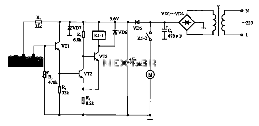
This automatic control mechanism ensures that crops receive water only when necessary, conserving water and promoting healthy plant growth. The design is modular, allowing for easy integration of additional features such as timers or remote monitoring systems, which can further enhance the functionality of the irrigation system. Automatic sprinkler control circuit It shows automatic sprinkler control circuit. The circuit mainly by the humidity sensor, a detection signal amplifying circuit (transistor V T1,, RR2, VT3), the power supply circuit (filter capacitor C2, the bridge conditioning circuit UR, the transformer T), and the like of the DC motor M. In the circuit, a humidity sensor for detecting moisture in the soil, the DC motor M for driving irrigation equipment operation.
After working for some time irrigation equipment, soil moisture for crop growth conditions to achieve at this time embodied in the humidity sensor circuit resistance value is small, this time VT1 conduction, and to provide operating voltage VT2 base. VT2 are turned on. vr2 after conducting direct VT3 base and emitter short-circuited, VT3 end, so that the relay coil Kl-l de-energized, and drive its normally open contact Kl-2 recovery normally open state, the DC motor power to stop jobs.
Sprinkler irrigation equipment stops. When soil moisture dries, moisture transfer resistance between Bo value increases, resulting VT1 base potential is low, this time off VT1, VT2 off, VT3 base provided by the current conduction, the relay coil Kl -l was electric pull and drive normally open contact Kl 2 is closed, the DC motor power and start working.
Related Circuits
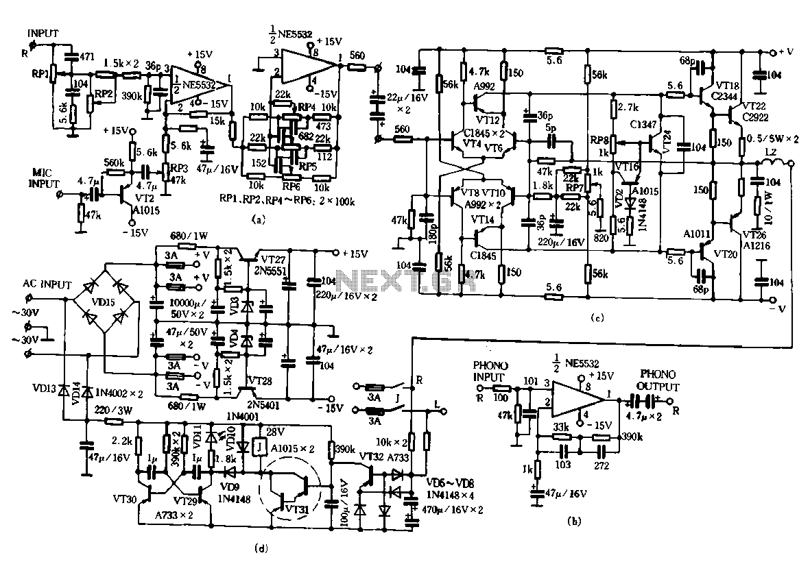
Only the R channel is shown, with the original reference PCB label. Figure (a) illustrates the front tone circuit, which consists of a common negative feedback operational amplifier in an RC circuit configuration. The microphone signal is amplified by...

This circuit is capable of generating up to 1 W of audio power to drive a speaker or horn. When the CDS cell is exposed to light, its resistance decreases, activating NOR gate (a). This activation causes gates (a)...
The DTMF codec stands for dual-tone multi-frequency codec. The multiple-channel infrared remote control switch circuit that incorporates the DTMF is depicted in the figure. It consists of an infrared remote control signal emitter, an infrared receiving signal amplifier, a...
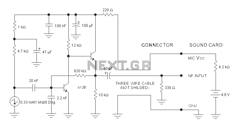
The sound card for a PC typically includes a microphone input, speaker output, and occasionally line inputs and outputs. The microphone input is specifically designed for dynamic microphones, accommodating an impedance range of 200 to 600 ohms. An adaptation...
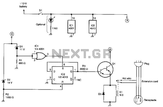
This circuit utilizes a pair of Zener diodes to monitor the voltage of a 12-V battery. When the voltage drops below 11 V, diode D1 ceases to conduct, causing pin 3 of flip-flop IC2 to go high. This action...
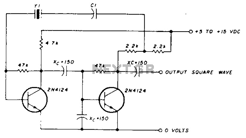
A transistor in series with capacitor C1 can be utilized to adjust the oscillator output frequency. The frequency may vary with changes in capacitance ranging from 20 pF to 0.01 µF, or as determined by the tuning capacitor. The...