
555 Timer IC for Square Wave Generator Application

The Square Wave Generator circuit utilizing the 555 timer IC is a versatile and widely used configuration in electronics. The 555 timer can operate in astable mode to generate a continuous square wave signal. In this configuration, the timer's output toggles between high and low states, creating a square wave.
The circuit typically consists of a 555 timer IC, resistors, a potentiometer for frequency adjustment, and capacitors for timing. The frequency and duty cycle of the output waveform can be controlled by the values of these passive components. The standard formula for calculating the frequency (f) of the output square wave is given by:
\[ f = \frac{1.44}{(R1 + 2R2) \cdot C} \]
Where:
- \( R1 \) is the resistance connected between pin 7 (discharge) and Vcc,
- \( R2 \) is the resistance connected between pin 7 and pin 6 (threshold),
- \( C \) is the capacitance connected between pin 6 and ground.
The potentiometer serves as a variable resistor, allowing for fine-tuning of the frequency output. By adjusting the potentiometer, the resistance value changes, thereby altering the timing intervals and consequently the frequency of the square wave produced.
The output from pin 3 of the 555 timer IC can be monitored using an oscilloscope. This connection enables visualization of the square wave, providing insight into its characteristics such as frequency, amplitude, and duty cycle. The oscilloscope also facilitates real-time adjustments and measurements, making it an invaluable tool for verifying the performance of the circuit.
In summary, the 555 timer IC in astable mode is an effective means of generating square wave signals. Through careful selection of component values and adjustments using a potentiometer, a wide range of frequencies can be achieved, making this circuit applicable in various electronic applications such as clock pulses, tone generation, and signal modulation.You can start to set your Square Wave Generator up using 555 timer IC through the circuit shown above. Find it match with the pinout of 555 timer IC. The osciloscope is then connected to the output of 555 timer IC in order to view the square wave. From the oscilloscope you can measure the wave frequency and verify it by varying the resistance in the potentiometer (source: utpa. edu ) 🔗 External reference
Related Circuits
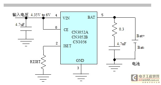
The CN3052A/CN3052B/CN3056 is a high-performance linear lithium battery management chip. It integrates a power transistor, eliminating the need for an external sense resistor and a choke flow diode for current sensing. Only a few peripheral components are required, and...
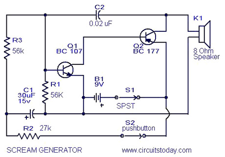
Multi Tone Alarm Description This is a simple and easy-to-build multi-tone alarm circuit that can be used in burglar alarms or sirens. The circuit is based on the dual op-amp MC1458 and LM380. The two op-amps inside the MC1458...
The circuit produces a clean sine wave signal suitable for audio testing or other applications requiring a high-quality sine voltage source. It utilizes a widely available dual operational amplifier, the Texas Instruments TL072CP. The component values yield an output...
Quartz crystals exhibit a unique property whereby their amplitude and phase characteristics repeat at frequencies that are uneven multiples of the fundamental frequency. Quartz crystals are widely utilized in electronic circuits due to their ability to generate precise frequencies. This...
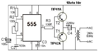
This 12V power inverter circuit can be utilized to power small devices that require 240 volts. It is particularly advantageous for operating 240-volt appliances using a 12-volt car battery. Unlike typical feedback oscillator inverters, this design employs a 555...
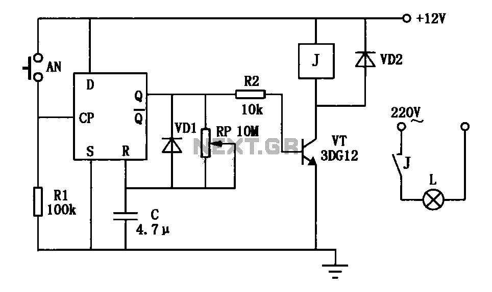
An exposure timer circuit is illustrated using D flip-flops, allowing for timing adjustments between 1 to 30 seconds. The D flip-flop circuit is connected to a one-shot timer. When exposure is required, pressing button AN generates a pulse that...