
Tone Generator Circuits
The multi-tone alarm circuit utilizes the MC1458 dual op-amp to generate distinct sound patterns suitable for security applications. The configuration of IC1a as a multi-vibrator allows for the generation of square waves, which are then processed by IC1b acting as an integrator to produce a triangular waveform. The LM380 serves as an audio amplifier to enhance the output sound level, making it suitable for alarm systems. The inclusion of switch S1 provides flexibility in selecting between the square and triangular wave outputs, allowing for customizable alarm tones.
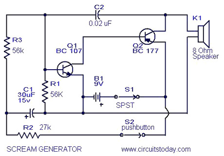
The simple sound generator circuit employs two transistors, Q1 and Q2, to create a high-frequency siren sound. The design allows for a momentary activation of the sound when switch S2 is pressed, creating a variable frequency output that diminishes upon release. This feature is particularly useful for alarms or warning signals, as it provides an attention-grabbing sound that can be adjusted based on the application.
The doorbell circuit utilizing the UM66 IC demonstrates a practical application of melody generation. By charging capacitor C1 upon pressing the push button, the circuit ensures that the melody plays fully without the need for continuous switch activation. The time duration of the melody can be adjusted by changing the resistance value of R1, providing additional customization for users.
The melody generator circuit based on the UM66 series further illustrates the capabilities of CMOS technology in low-power applications. The integrated ROM allows for pre-programmed melodies, which can be amplified for use in various devices, including toys and alert systems. The design ensures that the output sound is clear and audible while maintaining low energy consumption.
Lastly, the tone generator circuit, built around IC 8021, offers a straightforward solution for producing a ding-dong sound. The built-in ROM facilitates the generation of the sound upon activation, while the complementary transistor amplifier configuration enhances the output to drive either a piezoelectric tweeter or a standard speaker. This circuit is ideal for applications requiring simple auditory signals, such as doorbells or alerts.Multi Tone Alarm Description This is a simple and easy to build multi tone alarm circuit that can be used in burglar alarms or sirens. The circuit is based on dual op amp MC1458 and LM 380. The two op amps inside the MC 1458 are used to produce square and triangular waves. LM 380 is used to amplify the output. The first op amp IC1a is wired as an as table multi vibrator and second op amp IC1b is wired as an integrator, to make the square wave triangle. The two output square ans sine can be selected using switch S1 Simple Sound Generator Circuit Description This is a real scream generator circuit suitable for any purpose like alarm or car horn.
The circuit is based on two transistors Q1 and Q2. When you press the switch S2 the siren starts up moving to a high frequency. When the switch is released the tone slips down until you shift it up again by pushing the switch S2. Sound Generator Circuit Diagram with Parts List. Notes. Adjustment of tone quality can be obtained by different values for C2. If the alarm oscillates before S2 is pressed. The transistor is leaky, replace it. S1 can be used Doorbell Circuit Description Here is a simple and easy to build doorbell circuit using IC UM 66.
The details of UM 66 is given in the older post Melody Generator using UM 66 ³. This is a slight modification of that circuit. In the previous circuit you have to keep the switch pressed for making the IC play the full music. Here if once the push button is pressed C1 is charged and the transistor Q2 will keep the IC playing the music till it ends. The time for the IC to play depends on discharging time of C1 which can be set by R1. Set Melody Generator Circuit Description Here is a simple melody generator circuit you can make using an IC.
The UM66 series are CMOS IC`s designed for using in calling bell, phone and toys. It has a built in ROM programmed for playing music. The device has very low power consumption. Thanks for the CMOS technology. The melody will be available at pin3 of UM66 and here it is amplified by using Q1 to drive the speaker. Resistor R1 limits the base current of Q1 within the safe values. Capacitor C1 is meant for noise suppression. Notes Power supply must be between 1. 5V & 4. 5V. Do not Tone Generator Circuit Description Here we present a simple and low cost tone generator circuit, a ding dong bell suitable for calling bell purposes.
It is made around IC 8021. It is an 8 pin IC but only four pins are shown here. 8021 has an in-built circuitry to produce ding dong sound each time its pin 3 is pulled low. The sound is stored in a 4 bit ROM. A complementary-pair, two-transistor amplifier is used to amplify the sound to a fair level of audibility. A piezoelectric tweeter or an 8-ohm, 500mW speaker can be used at the output. Each 🔗 External reference
Related Circuits

A voltage comparator is a device that compares the voltages at its two inputs and generates an output based on the comparison. It produces a high output when the positive input exceeds the negative input and a low output...
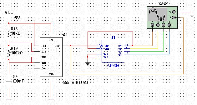
This tutorial explores a common digital concept using the NI Multisim software environment. It examines a four-bit counter that uses a 555 timer IC to generate the clock signal. This tutorial takes less than 30 minutes to complete and...
A 1200 Watt lamp dimmer circuit is designed to control lighting levels and is capable of managing up to 1200 Watts. This circuit utilizes the Q4015LT, which combines a Diac and a Triac for 230V dimming applications. It serves...
NOTE: There is no guarantee as to the suitability of said circuits and information for any purpose whatsoever other than as a self-training aid. I.E. If it blows your equipments, trashes your hard disc, wipes your backup, burns your...
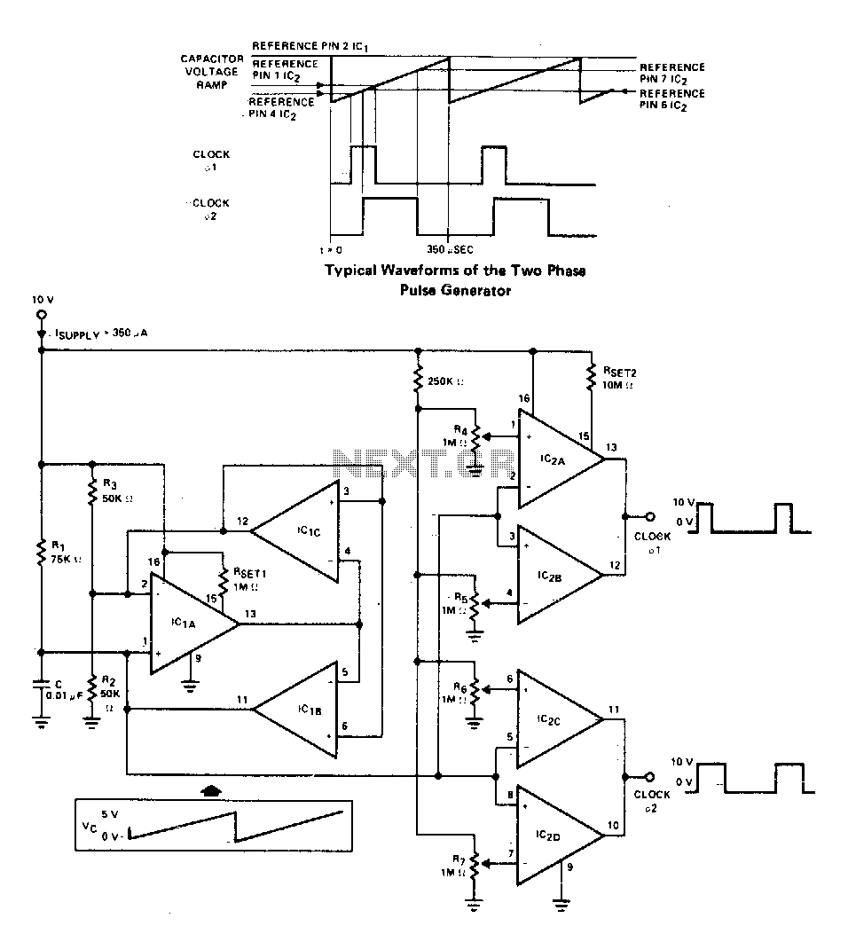
A two-phase clock generator utilizes two L161 integrated circuits to produce pulses with adjustable widths and phase relationships. Additionally, a ramp generator supplies input to two variable window comparators, which are configured using IC2A-IC2B and IC2C-IC2D, respectively. The two-phase clock...
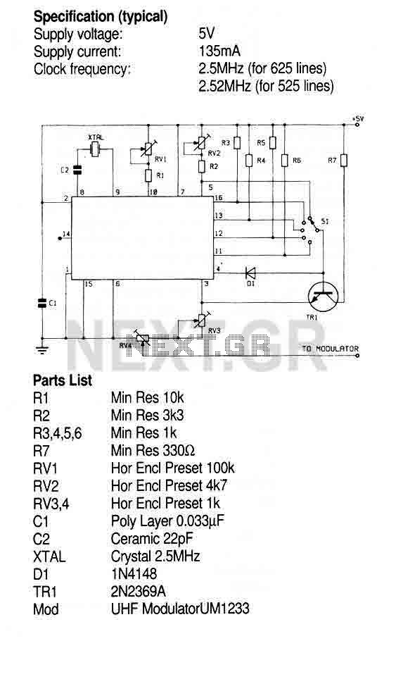
This Circuit uses the ZNA234E IC which makes available all the waveforms necessary to produce the crosshatch, dot and greyscale test patterns on a television screen. The composite video output can be injected directly into the video input of...
Warning: include(partials/cookie-banner.php): Failed to open stream: Permission denied in /var/www/html/nextgr/view-circuit.php on line 713
Warning: include(): Failed opening 'partials/cookie-banner.php' for inclusion (include_path='.:/usr/share/php') in /var/www/html/nextgr/view-circuit.php on line 713