
555 Timer IC For Tachometer Circuit Project

The Tachometer Circuit utilizes a 555 Timer configured in monostable mode to measure the rotational speed of an object, typically in revolutions per minute (RPM). The circuit operates by detecting the pulses generated by a rotating shaft, which are then converted into a corresponding voltage signal that can be easily interpreted.
In the circuit, the 555 Timer is connected to a sensor that produces a pulse for each rotation of the shaft. This pulse is fed into the trigger input of the 555 Timer, causing it to output a high signal for a duration determined by the resistor and capacitor values connected to it. The output pulse width is proportional to the frequency of the input pulses, which directly correlates to the speed of rotation.
The configuration includes a power supply, typically 5V to 15V, which powers the 555 Timer. The timing components, a resistor (R) and a capacitor (C), are selected based on the desired time constant for the output pulse. The relationship between the timing components and the output frequency can be expressed using the formula:
\[ T = 1.1 \times R \times C \]
where \( T \) is the time period of the output pulse.
To display the measured RPM, a digital voltmeter or an analog meter can be connected to the output of the 555 Timer. The output voltage can be calibrated to correspond to specific RPM values, allowing for easy reading and interpretation of the results.
Overall, this Tachometer Circuit is a practical application of the 555 Timer IC, showcasing its versatility in timing applications and its ability to interface with other components to create a functional speed measurement system.The following circuit shows about Tachometer Circuit Project. This circuit built based on the 555 Timer IC. Features: monostable IC, voltage .. 🔗 External reference
Related Circuits
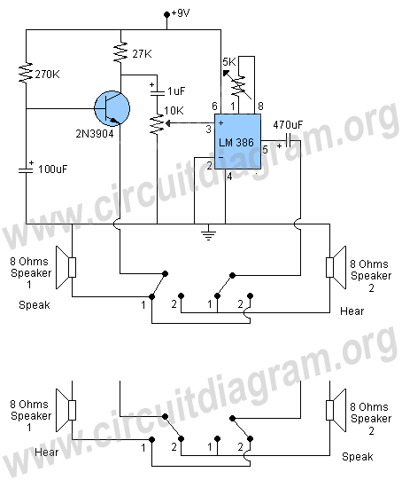
The circuit described is a simple intercom system that utilizes a single LM386 integrated circuit, a 2N3904 transistor, and several additional components. The LM386 is a widely recognized amplifier IC commonly employed by electronics enthusiasts in audio applications. In...
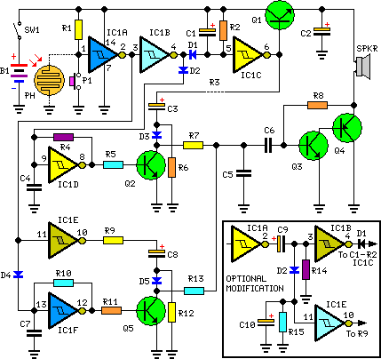
This circuit generates dual-tone bell ringing similar to most doorbell units. It can be used in various applications beyond just doorbells. Several options will be provided in the notes to accommodate different needs. The circuit, as depicted in the...
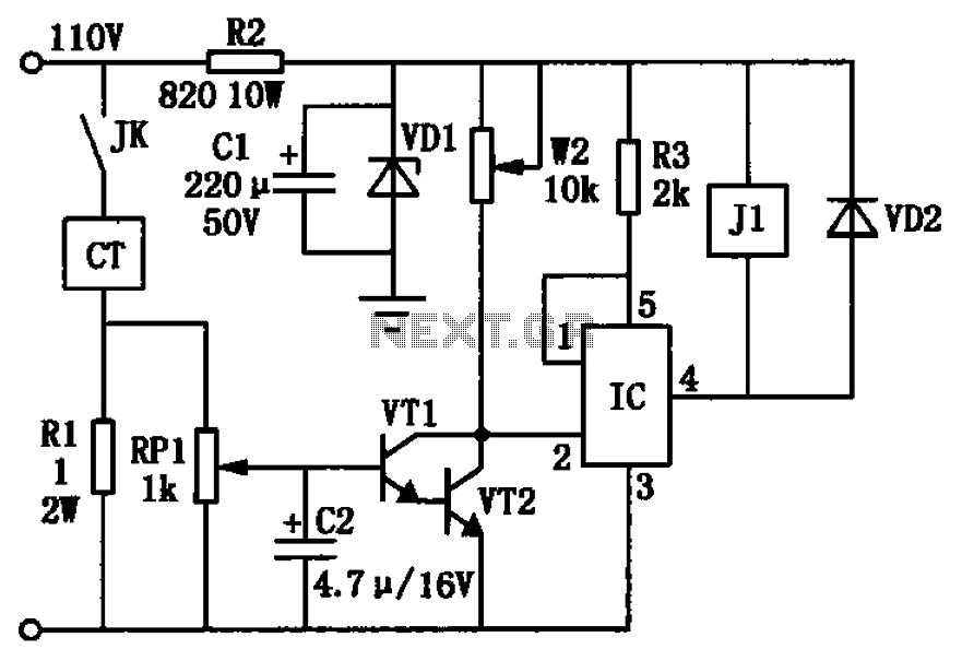
The circuit depicted in the figure utilizes a +24V power supply derived from a 110V power source through an electromagnetic chuck. When the electromagnetic chuck circuit is activated, the contact JK closes, enabling the operation of the magnetic chuck....
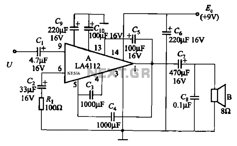
Audio power amplifier circuit utilizing the LA4112 integrated power amplifier along with additional components as shown in the figure. The audio power amplifier circuit based on the LA4112 integrated power amplifier is designed to deliver high-quality audio amplification for various...
Precious metals can sometimes be buried too deep to be detected without complex devices. However, smaller pieces of precious metals located near the surface can often be found using simpler methods. Many individuals are drawn to the prospect of...
This circuit diagram illustrates a setup for two flashing LEDs designed for various applications, including model construction and recreational uses. It features adjustable flashing speeds controlled by two potentiometers. The circuit comprises a combination of active and passive components....