
Audio power amplifier circuit LA4112 composition

The audio power amplifier circuit based on the LA4112 integrated power amplifier is designed to deliver high-quality audio amplification for various applications. The LA4112 is a versatile and efficient amplifier that can provide output power suitable for driving speakers in consumer electronics, such as home audio systems, televisions, and portable audio devices.
The circuit typically includes input and output stages, power supply connections, and various passive components that enhance performance and stability. The input stage usually consists of capacitors and resistors that filter and condition the audio signal before it is amplified. The LA4112's internal circuitry manages gain and feedback, ensuring linear amplification and minimizing distortion.
Power supply decoupling is critical in such circuits, and capacitors are employed to stabilize the voltage supply, reducing noise and improving overall performance. The output stage is connected to the speakers, and it may include additional components like inductors or output capacitors to optimize the frequency response and protect against overloading.
Thermal management is also a significant consideration, as the LA4112 can generate heat during operation. Adequate heat sinking or thermal pads may be necessary to maintain safe operating temperatures and ensure reliability over prolonged use.
Overall, the LA4112 audio power amplifier circuit represents a robust solution for audio amplification, combining efficiency with high fidelity, making it suitable for a wide range of audio applications. Audio power amplifier circuit from LA4112 integrated power amplifier and other components of FIG.
Related Circuits
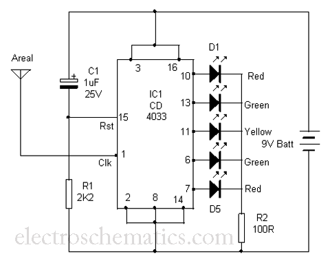
This is a simple tool designed to measure the level of radiation emitted by electrical or electronic devices. The circuit utilizes LEDs to create a running light pattern when it detects electromagnetic radiation from a source. It can detect...
A modulated current is supplied by the integrated rotational speed sensor KMI 15/x. This current signal needs to be converted into a ground-referenced voltage signal. The KMI 15/x sensor operates by generating a modulated current proportional to the rotational speed of...
This application note provides a concise overview of power amplifier theory and presents simulation results that offer insights into the operation of the power amplifier across all of MAXIM's LFRF transmitters and transceivers. Power amplifiers are critical components in communication...
The MAX1846 inverting circuit implements a switch-mode power supply that provides -15V at 0.5A output from a 4.5V to 12V input. This circuit incorporates additional components beyond the minimum implementation. C20 introduces a pole to compensate for the ESR-zero...
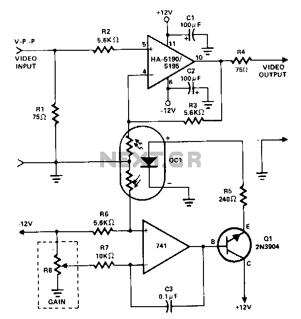
This amplifier utilizes a cascaded operational amplifier (op amp) integrator and a transistor buffer, Q1, to drive the gain control element. With a minor modification, the HA-5190/5195 stage is configured as a conventional non-inverting op amp and includes input...
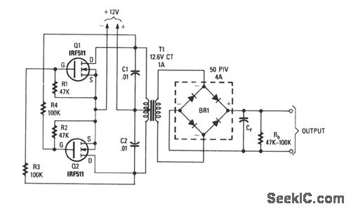
This inverter is capable of delivering high-voltage AC or DC, utilizing a rectifier and filter, with outputs reaching several hundred volts. The transformer T1 features a power rating of 12.6 to 440 V, with the primary and secondary windings...