
Machine magnechuck under current protection circuit diagram
The described circuit operates as a current monitoring and control system for an electromagnetic chuck, ensuring safe operation by automatically managing the power supply based on current draw. The circuit's design features a feedback mechanism that closely monitors the current through the electromagnetic chuck. The sampling resistor R1 plays a crucial role in providing a voltage drop proportional to the current flowing through the chuck, which is then processed by the potentiometer RPl to adjust the sensitivity of the system.
Transistor VT1 is configured as a current amplifier, and its output is fed into VT2, which functions as a further amplification stage. This configuration not only enhances the signal but also allows for rapid switching of the power control IC. The TWH8751 IC is selected for its suitability in handling the required voltage and current levels while providing the necessary logic to operate the relay J1 effectively.
Relay J1 acts as a switch that controls the power to the machine feed circuit. When the electromagnetic chuck operates within safe limits, the relay remains energized, allowing the machine to function. However, should the current exceed the predetermined threshold, the IC will disable the relay, cutting off power to the machine and thus preventing potential hazards associated with overcurrent conditions.
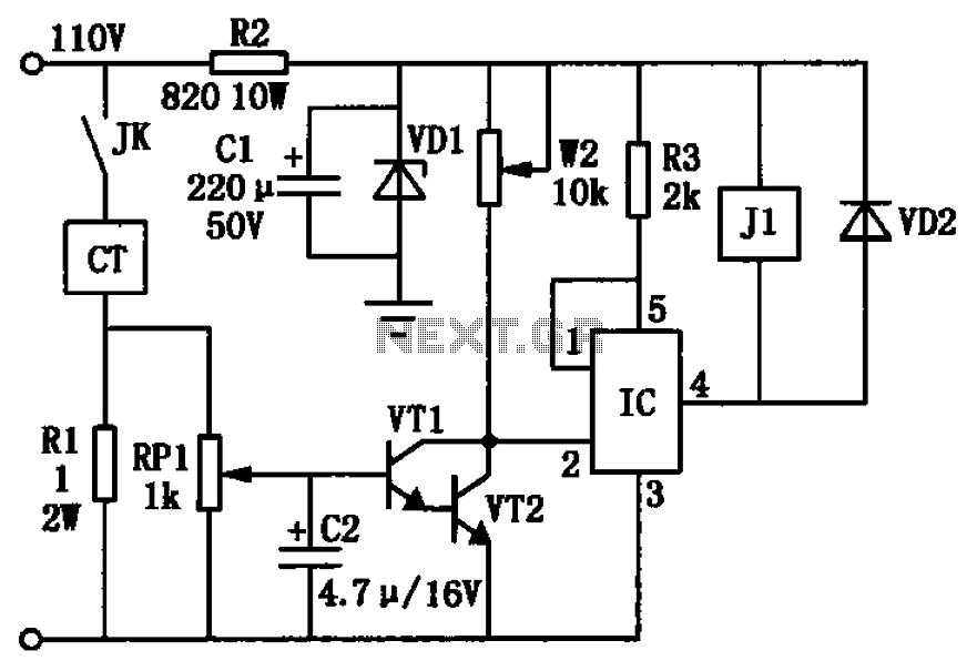
The choice of components, including the specific transistors and diodes, is critical to the circuit's performance and reliability. Each component must be rated appropriately for the expected current and voltage levels to ensure the overall integrity of the system. The circuit's design is aimed at providing robust protection and control for applications involving electromagnetic chucks in various industrial settings. Circuit shown in Figure, + 24V power supply is obtained by the electromagnetic chuck 110V power down. When the electromagnetic chuck circuit make contact JK closed magnechuck C T power of work, the rated current is about l.4A (strong current disk will be bigger). At this point in the series circuit of the electromagnetic chuck sampling resistor Rl will have 1.4V voltage drop, and then after the sample is applied to the potentiometer RPl sampling transistor VTl input circuit by VTl, VT2 composite amplification. VTl, high magnification VT2 composite post, VT2 collector step closer to a potential change signal, the power switch integrated circuit IC can be quickly turned on or off.
After sampling circuit from the normal signal voltage is amplified, so VTl, the collector potential VT2 close to 0V, ICs feet at low potential, feet turn, relay J1 was electric. Its moving together contact closure, so that the machine feed work. When 90% of the electromagnetic chuck current is less than the rated current (value adjustable), feet off the IC, J1 power, machine power feed circuit at the same time, feeding system to stop working, thus avoiding accidents.This circuit IC selects TWH8751 type, VTl type selection 9013, VT2 selection 3DGl2 type, VDl choose 24V, 1W, VD2 selected lN4148 relay J1 selection JTX-24 type.
Related Circuits

This circuit is used to select modes of operation. The accelerometer is utilized to generally move the snake arm, while the Hall effect sensors are designed to enable various functions. The circuit described incorporates an accelerometer and Hall effect sensors...
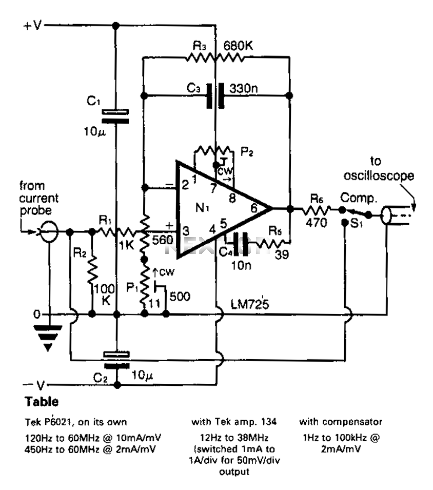
A clip-on current probe, like the Tektronix P6021, is a valuable tool for displaying current waveforms on an oscilloscope. However, it has limitations in low-frequency response. Specifically, the P6021 is sensitive to a range of 2mA/mV, and frequencies below...
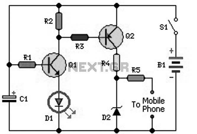
An ideal mobile charger utilizing 1.5-volt pen cells to charge mobile phones while traveling. This charger can replenish a cell phone battery three to four times in locations where AC power is unavailable. Most mobile phone batteries are rated...
There are a number of ways to obtain the low voltages required to run small projects from the wall power outlet. The simplest way is to buy a factory-built molded supply which is designed to plug directly into the...
This example presents a switch DC regulated power supply circuit designed for buck-mode +5V applications. It consists of a power supply circuit, an impulsator, a voltage sampling or pulse width modulation circuit, and a buffering driver circuit, as illustrated...

Conducting pipe rechargeable long delay control circuit. An adjustment potentiometer RP can delay up to several tens of seconds. The conducting pipe rechargeable long delay control circuit is designed to manage the timing of electrical signals, allowing for a delay...