
555 Tone Generator Circuit (8 ohm speaker)
The described circuit utilizes the 555 timer IC in astable mode to generate a square wave signal, which is essential for producing audio tones. The configuration includes two distinct circuits: one employing a transistor to amplify the output current for driving the speaker, and the other connecting the speaker directly to the timer's output. The first circuit's use of an NPN transistor allows for greater power handling capabilities, making it suitable for driving low-impedance loads like an 8-ohm speaker without exceeding the current limitations of the 555 timer.
In the first circuit, the frequency of oscillation is determined by the resistors R1 and R2, and the capacitor C. The formula for frequency highlights the relationship between these components, indicating that by adjusting R2, one can effectively change the frequency output. The inclusion of a capacitor at the transistor's base serves to smooth the switching characteristics, thereby minimizing unwanted voltage spikes that could arise from the inductive nature of the speaker.
The second circuit demonstrates a more straightforward approach by directly connecting the speaker to the 555 timer output. The 100 µF capacitor plays a crucial role in this setup, as it allows the output to alternate, effectively transforming the DC output of the timer into an AC signal, which is more suitable for audio applications. The series resistor serves as a current-limiting device, ensuring that the output does not exceed the safe operating limits of the timer, particularly at higher supply voltages.
Overall, this circuit exemplifies a practical application of the 555 timer in generating audio signals, with considerations for current handling and frequency adjustment through component selection. The versatility of the 555 timer allows for various modifications to suit different audio output requirements, making it a valuable component in electronic sound generation projects.This is a basic 555 squarewave oscillator used to produce a 1 Khz tone from an 8 ohm speaker. In the circuit on the left, the speaker is isolated from the oscillator by the NPN medium power transistor which also provides more current than can be obtained directly from the 555 (limit = 200 mA). A small capacitor is used at the transistor base to sl ow the switching times which reduces the inductive voltage produced by the speaker. Frequency is about 1. 44/(R1 + 2*R2)C where R1 (1K) is much smaller than R2 (6. 2K) to produce a near squarewave. Lower frequencies can be obtained by increasing the 6. 2K value, higher frequencies will probably require a smaller capacitor as R1 cannot be reduced much below 1K. Lower volume levels can be obtained by adding a small resistor in series with the speaker (10-100 ohms).
In the circuit on the right, the speaker is directly driven from the 555 timer output. The series capacitor (100 uF) increases the output by supplying an AC current to the speaker and driving it in both directions rather than just a pulsating DC current which would be the case without the capacitor. The 51 ohm resistor limits the current to less than 200 mA to prevent overloading the timer output at 9 volts.
At 4. 5 volts, a smaller resistor can be used. 🔗 External reference
Related Circuits
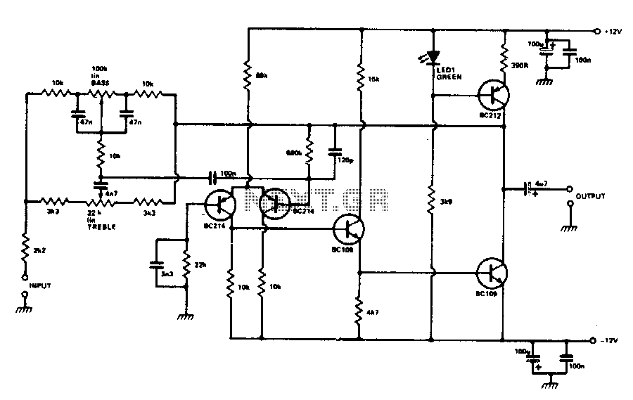
The circuit utilizes an inverting operational amplifier configuration with discrete transistors to address issues such as inadequate slew rate, significant distortion, and elevated noise levels. The output stage is powered by a constant current source, which is biased using...
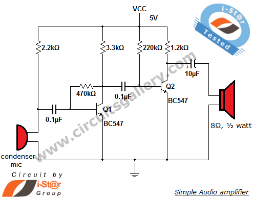
The output of the condenser microphone is coupled through a 0.1 µF coupling capacitor, which serves to eliminate DC components from the audio signal. Transistor Q1 is configured in a collector-to-base biasing mode, achieved with a 470kΩ resistor. This...
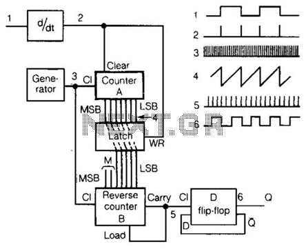
An input rectangular signal is differentiated to produce short impulses from its edges. These impulses transfer the content of counter A to a latch that clears the counter after a very brief period. Counter A counts impulses at a...
A small delay circuit is required to produce a pulse for a cell phone vibrational motor every 0.75 seconds, with an adjustable delay time ranging from 4 to 10 seconds. The circuit will be powered by a 9-volt battery. To...
This page provides basic information about voltage comparator integrated circuits and is to act as reference material for other circuits. The circuits shown are based on the LM339 Quad Voltage Comparator chip or the LM393 Dual Voltage Comparator chip....
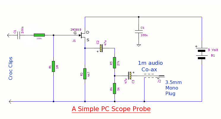
This simple PC scope probe functions as a FET follower, featuring high input impedance and low output impedance to match a microphone or line input socket on a PC or laptop. This design allows for practical examination of waveforms...
Warning: include(partials/cookie-banner.php): Failed to open stream: Permission denied in /var/www/html/nextgr/view-circuit.php on line 713
Warning: include(): Failed opening 'partials/cookie-banner.php' for inclusion (include_path='.:/usr/share/php') in /var/www/html/nextgr/view-circuit.php on line 713