
555Circuit and Breadboard Schematic

To create a reliable electronic circuit, it is essential to meticulously verify all connections as indicated in the circuit diagram and breadboard schematic. These documents serve as critical references throughout the assembly process, ensuring that components are connected correctly to avoid potential issues such as short circuits or component damage.
The circuit diagram typically provides a visual representation of the electrical connections between components, illustrating how each part interacts within the overall system. It includes symbols for various components such as resistors, capacitors, diodes, and integrated circuits, along with their respective values and ratings. The breadboard schematic complements this by offering a practical layout for physically arranging the components on a breadboard, which is often used for prototyping circuits.
When assembling the circuit, it is advisable to follow these steps:
1. **Component Identification**: Gather all necessary components as per the schematic. Ensure that each component is in good condition and matches the specifications outlined in the circuit diagram.
2. **Breadboard Layout**: Begin placing components on the breadboard according to the schematic. Pay close attention to the orientation of polarized components, such as electrolytic capacitors and diodes, to ensure they are installed correctly.
3. **Wiring Connections**: Use jumper wires to connect the components as shown in the circuit diagram. It is crucial to maintain a neat layout to prevent confusion and facilitate troubleshooting.
4. **Verification**: After all components are placed and connected, double-check every connection against the circuit diagram. This includes confirming that all components are properly powered and grounded.
5. **Testing**: Once verification is complete, power the circuit and test its functionality. If issues arise, refer back to the circuit diagram and breadboard schematic to identify any potential miswirings.
Following these steps will enhance the reliability of the assembled circuit and contribute to its successful operation.Make sure to double-check your connections using the circuit diagram and breadboard schematic (download from these links). You can use this while you.. 🔗 External reference
Related Circuits

The LMP91200 is a configurable sensor analog front-end (AFE) designed for managing low-power analytical sensing applications, specifically for 2-electrode sensors. This device offers all the necessary functionality to detect changes based on a delta voltage from the sensor. It...
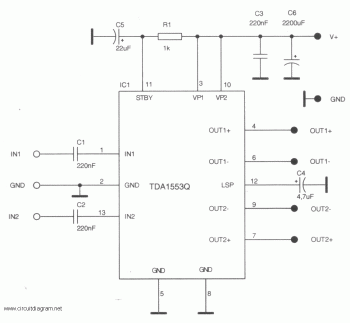
This is a schematic diagram of a stereo audio amplifier for a car. The circuit is powered by a single IC, the TDA1553, along with some external components. This IC is designed to manage the stereo car audio system....
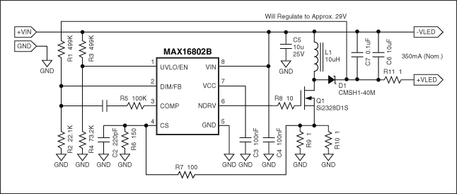
Flyback LED drivers are versatile as they can be utilized in applications with input voltages either above or below the necessary output voltages. They feature a straightforward circuit configuration that maintains a constant LED current without the need for...
The amplifier circuit is well-suited for use in subwoofer speakers due to its robust performance. This circuit utilizes an integrated circuit (IC) based on the STK series. It can be employed in vehicles equipped with speakers or a subwoofer...
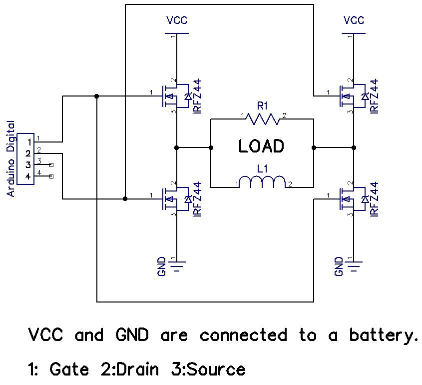
The H-Bridge is a circuit that can drive a motor in both forward and reverse directions. It can be a straightforward circuit that requires only a few components. The H-Bridge circuit is a fundamental configuration used in motor control applications,...
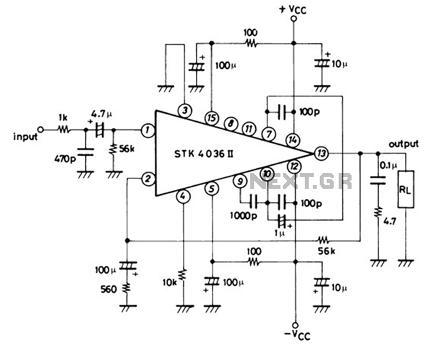
This is a 50-watt audio power amplifier circuit based on the single IC STK4036II. A heatsink is required to prevent overheating of the IC. The amplifier circuit provides good sound quality at an affordable price and is easy to...