
H-Bridge on a Breadboard

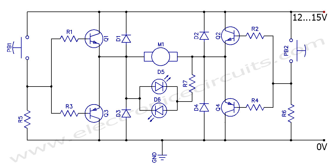
The H-Bridge circuit is a fundamental configuration used in motor control applications, allowing for bidirectional operation of DC motors. It typically consists of four switches, which can be implemented using transistors or MOSFETs. These switches are arranged in an "H" formation, hence the name "H-Bridge."
To drive the motor forward, two switches on one side of the bridge are closed while the other two switches are opened. This creates a voltage potential across the motor terminals in one direction. Conversely, to reverse the motor's direction, the opposite pair of switches is activated, allowing current to flow in the opposite direction through the motor.
Control of the H-Bridge can be achieved using various methods, including microcontrollers, which provide PWM (Pulse Width Modulation) signals to modulate the speed and direction of the motor. Additionally, diodes are often included in the design to protect the circuit from back EMF generated by the motor during operation, ensuring reliability and longevity of the components.
In more advanced applications, H-Bridges can be integrated into larger systems with feedback mechanisms for precise control of motor speed and position. The simplicity and versatility of the H-Bridge make it a popular choice in robotics, automation, and various consumer electronics where motor control is required.The H-Bridge is a circuit which can drive a motor in forward and reverse. It can be a very simple circuit that requires only a handful of components.. 🔗 External reference
Related Circuits
This circuit can control the direction of a DC motor, allowing it to operate in both clockwise and counterclockwise directions (forward and backward). The described circuit employs an H-bridge configuration, which is essential for reversing the polarity of the voltage...
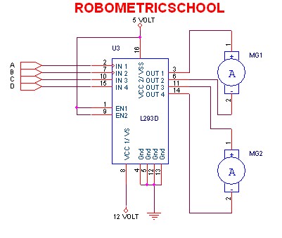
The electronic schematic of a DC motor driver using the L293D, as illustrated in Figure 2, enables the control of two DC motors continuously. It allows for one motor to rotate clockwise while the other rotates counterclockwise. Additionally, all...
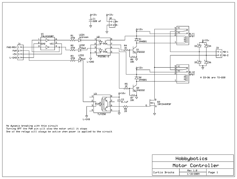
The HandyBoard operates both pads using the positive supply from the battery. When one of the motors is intended to turn, the HandyBoard activates the corresponding pin to 0V. The voltage difference between the two pads causes the motor...
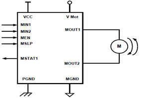
The schematic presented illustrates a 5A H-Bridge Module designed for the operation of a single Bipolar DC motor. The H-Bridge Module includes a header set (J2) and a connector terminal set (J1). Below is the pinout description for the...
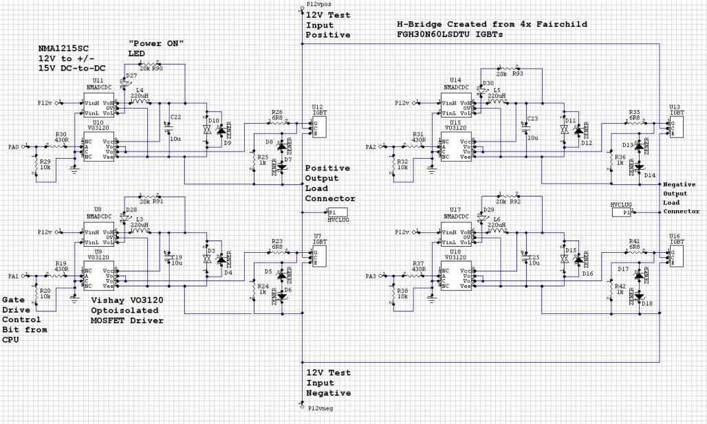
The Murata NMC1215SC DC/DC converters in a CPU-controlled H-Bridge design are experiencing repeated failures, with no obvious signs of the cause. The Murata NMC1215SC is a step-down DC-DC converter renowned for its efficiency and compact design, making it suitable for...
Develop a cost-effective high-current circuit that utilizes PWM. The design includes flyback diodes to protect the MOSFET from the back EMF generated by the motor when the power is switched on and off via the PWM signal. This configuration...