
5A Lab Power Supply With Digital Readout
The power consumption of the LM338 is a critical consideration. The TO-3 version can dissipate approximately 50W of heat with an appropriate heatsink, while the TO-220 version can handle around half that amount due to increased thermal resistance. A single LM338 cannot provide 5A of continuous output current at voltages lower than 10V if the input voltage is fixed at 20V. To achieve the required 5A current across the input voltage range while remaining within the thermal limits of the LM338, the input voltage must be adjusted in accordance with the output voltage. A practical approach is to employ a comparator with hysteresis to control a relay, allowing the input voltage to the regulator to switch between the two transformer windings (10V and 20V) based on the output voltage. More switching points could be added, but this would complicate the design, and multi-tap transformers are less common. Based on the given parameters, the switching point is set at approximately 7 volts with a hysteresis of 1V. When the output voltage is below 7V, the 10V output from the transformer is selected, while the 20V output is chosen when the voltage exceeds 7V. By adapting the input voltage to the current output voltage, maximum power dissipation of the LM338 is significantly minimized. A tool is available to assist in calculating the desired trip point. To maintain a compact heatsink, forced-air cooling was implemented. The cooling fan is regulated by another comparator, and by adjusting the potentiometer, the desired temperature for the fan to turn on or off can be set. Hysteresis is essential to prevent the fan from cycling on and off continuously near the temperature threshold. The LM338 circuit utilized is nearly identical to the reference design.A used 250VA power transformer that was removed from equipment a couple of weeks ago. The transformer has a dual 10V AC output and a few auxiliary voltage outputs. The 10V winding is rated at 10A, I thought it would be perfect for a high current power supply project. For this particular build, I used the reference design for LM338 5A adjustable linear regulator as the base.
Rather than designing digitally controlled voltage adjustment circuitry (e. g. via DAC), I decided to just use the simple resistor-potentiometer voltage control mechanism and add the digital voltage/current monitoring portion. Here are some of my thoughts behind this reasoning: By adding the digital voltage adjustment functionality via the three terminal regulator`s Adj pin, we would have increased the complexity of the control loop.
In a power supply, the reliability of the control loop is essential to the stability of the output voltage. If the Adj pin somehow becomes floated due to circuit malfunction, the result could be disastrous as the input voltage would be applied directly to the load.
Also the stability and the accuracy of the external reference affect the accuracy and the ripple rejection of the power supply as well. This must be taken in to consideration when using a DAC or PWM circuitry to drive the linear regulator`s Adj pin.
Last but not least, since the output voltage of the linear voltage regulator would essentially be controlled by the MCU, adequate filtering and monitoring (e. g. via watchdog timer) as well as careful designing of the board layout are usually needed for the MCU circuitry to work reliably.
Given the above thoughts, I decided to keep the core circuitry as simple as possible using the reference design and using the MCU only for current and voltage measurements. That said, if you intend to build a digitally controlled power supply, you can hop over to Dave`s site.
He has series of videos on how to design and build a digitally controlled power supply. The very first thing comes to my mind is the power consumption of the LM338. The TO-3 version of LM338 can dissipate around 50W heat with the proper heat sink. The TO-220 version can handle roughly half of that due to the increased thermal resistance. In either case, a single LM338 would not be able to provide 5A of continuous output current at voltages lower than 10V if the input voltage is pegged at 20 volts. In order to obtain the desired 5A current over the input voltage range and stay within the thermal envelop of LM338, the input voltage needs to be adjusted accordingly when the output voltage changes.
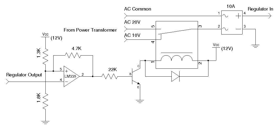
A simple method to achieve this is to use a comparator with hysteresis to drive a relay so that the input voltage to the regulator can be switched between the two windings of the power transformer (in this case, the input voltage is switched between 10V and 20V depending on the output voltage). More switch points are also possible, but the design would be more complicated and multi-tap transformers are harder to find.
Using the parameters given above, the switching point is at around 7 volts with a hysteresis of 1V. When output voltage is below 7V, the 10V output from the transformer is selected and when the voltage is above 7V the 20V output from the transformer is selected. By adjusting the input voltage according to the current output voltage, the maximum power dissipation of the LM338 is significantly reduced.
You can use this tool to calculate your desired trip point. To keep the heat sink small, I employed forced-air cooling. The cooling fan is controlled by another comparator (see circuit below) and by adjusting the potentiometer, you can achieve the desired fan on/off temperature. The hysteresis is necessary so that the fan does not turn on and off constantly when the temperature is near the tripping point.
As mentioned earlier, the actual LM338 circuit I used is almost identical to the reference de 🔗 External reference
Related Circuits
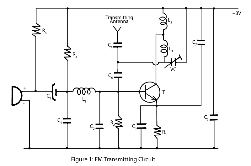
A simple and powerful FM transmitter is an interesting project that utilizes one transistor and operates within a frequency range of 100 MHz. The circuit diagram includes a description of the FM transmitter and various related interesting projects. The FM...
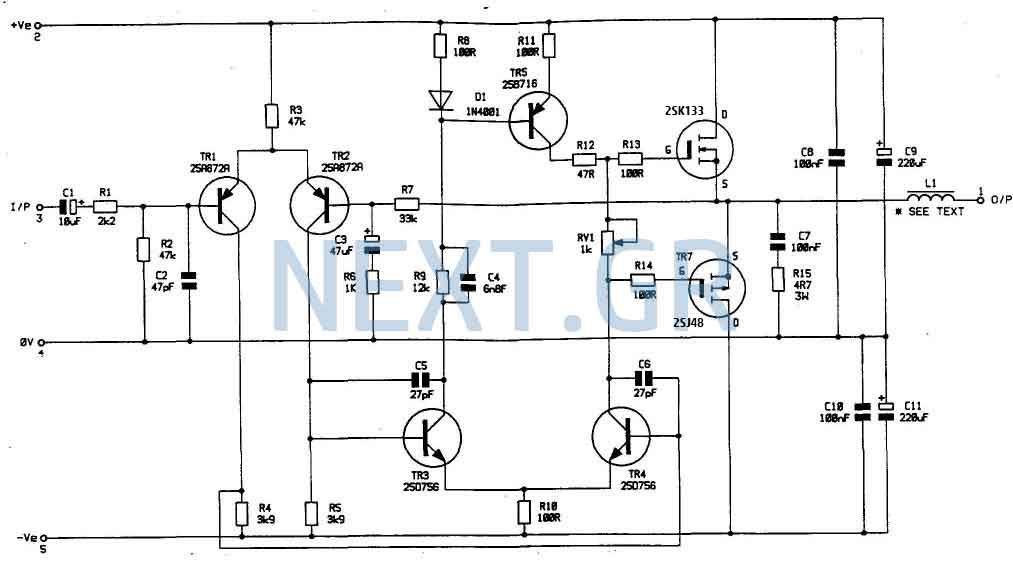
In my opinion that is the best buildable high power amplifier out there. Quality of sound is just remarkable. This is a real bomb proof amplifier like the best Valve amps. Power supply circuit is also shown. Now lets...
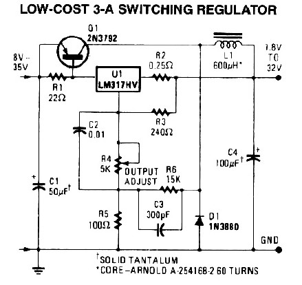
R2 sets the output voltage. The maximum current is determined by the value of R3: the over-current protection circuitry inside the LM723 senses the voltage across R3 and starts shutting the output stage off as soon as this voltage...

A repertory dialer phone contains a library of phone numbers that can be entered and dialed, allowing access to up to fifteen frequently used numbers. It also includes the capability to store the last dialed number or an additional...
The following diagram illustrates a 50W offline switching power supply circuit design. The circuit is powered by a MOSFET, specifically the BUZ80A/IXTP4N8 for a 220V AC voltage input and the GE IRF823 for a 110V AC input voltage. The...
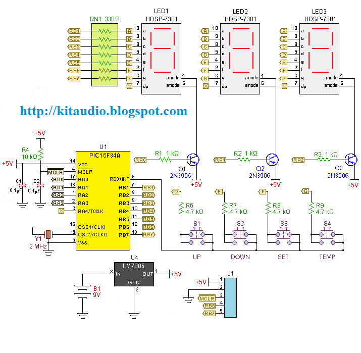
Redesign a complex solution using minimal external components, resulting in a low-cost application that provides high-precision measurements. This digital thermometer microcontroller project utilizes a watchdog timer function to measure temperature. The watchdog timer (WDT) on all PIC microcontrollers has...
Warning: include(partials/cookie-banner.php): Failed to open stream: Permission denied in /var/www/html/nextgr/view-circuit.php on line 713
Warning: include(): Failed opening 'partials/cookie-banner.php' for inclusion (include_path='.:/usr/share/php') in /var/www/html/nextgr/view-circuit.php on line 713