
simple and powerful FM transmitter

The FM transmitter circuit typically consists of a few essential components, including a transistor, resistors, capacitors, and an antenna. The core of the circuit is the transistor, which functions as an oscillator to generate the desired frequency. The circuit can be powered by a low voltage power supply, making it suitable for various applications.
The operation begins with the modulation of an audio signal, which is fed into the base of the transistor. This audio signal can originate from various sources, such as a microphone or an audio player. The transistor amplifies the audio signal, and through the use of capacitors and inductors, the circuit converts the audio modulation into an FM signal.
The design typically includes a feedback loop to stabilize the oscillation frequency and improve signal quality. The output of the transistor is then connected to an antenna, which radiates the FM signal over a specified range. The choice of antenna type and length can significantly affect the transmission distance and clarity of the signal.
In summary, the FM transmitter circuit is a straightforward yet effective project that demonstrates fundamental principles of electronics, including modulation, amplification, and RF transmission. It serves as an excellent educational tool for those interested in exploring the fields of radio frequency communications and circuit design.simple and powerful FM transmitter is a interesting project using one transistor range of 100 M circuit diagram with description of FM transmitter various interesting project. 🔗 External reference
Related Circuits
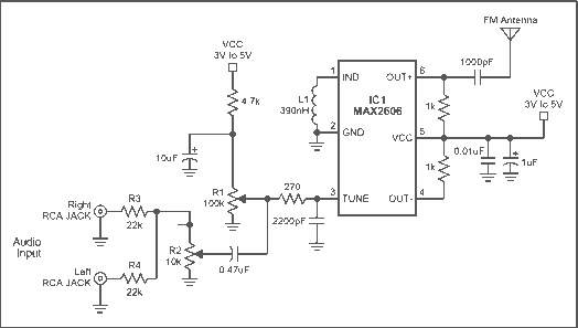
A simple FM transmitter links your home-entertainment system to a portable radio that can be carried around the house and into the back yard. For example, you can play music on the CD changer in your living room, and...
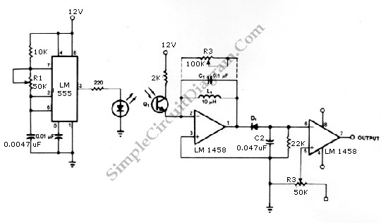
The infrared transmitter and receiver circuit depicted in the schematic diagram below can function as a remote control. The transmitter primarily operates as an oscillator. The infrared transmitter and receiver circuit is designed to facilitate wireless communication through infrared signals,...
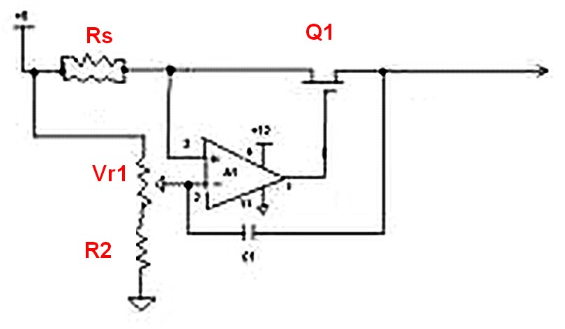
Assuming a 5V output can be achieved after adjusting the potentiometer, will the 240-ohm resistor limit the current, or is there a need to add additional components? If it does limit the current, it is expected that the power...
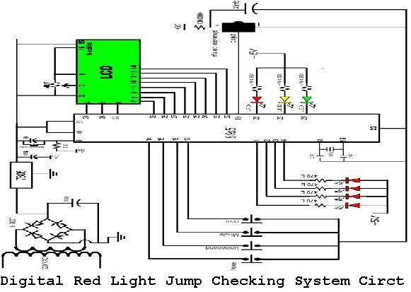
A digital red light jump checking system with an RF transmitter. This project allows for the tracking of vehicles that run red lights by capturing their license plate numbers and the time of the violation. The digital red light jump...

This circuit is a simple mixer circuit that can mix two signal channels into one output channel. It utilizes a codec circuit to convert stereo audio into mono audio. The circuit can also increase the number of channels by...
This is a simple single-zone burglar alarm circuit. Its features include automatic exit and entry delays and a timed bell/siren cut-off. It is designed to be used with the usual types of normally-closed input devices such as magnetic reed...