
5V/1A Power Supply

The circuit described operates with an input voltage of 220V AC, which is a common voltage level for household and industrial power supplies in many regions. The output of the circuit is a regulated 5V DC, suitable for powering low-voltage electronic devices such as microcontrollers, sensors, and other digital components. The current specification indicates that the circuit can supply a maximum of 1A at the output.
To achieve this voltage conversion from 220V AC to 5V DC, a typical design would include several key components. Initially, the AC voltage would be fed into a step-down transformer, which reduces the high voltage to a lower AC voltage level suitable for further processing. Following the transformer, a bridge rectifier circuit composed of four diodes would convert the AC voltage into pulsating DC.
After rectification, a smoothing capacitor would be employed to reduce the ripple voltage, providing a more stable DC output. To ensure that the output voltage is precisely regulated at 5V, a linear voltage regulator or a switching regulator may be integrated into the circuit. A linear regulator, such as the LM7805, can provide a simple solution for achieving the desired output voltage, while a switching regulator may offer higher efficiency, especially under varying load conditions.
Additionally, it is important to incorporate safety features such as fuses or circuit breakers to protect against overcurrent scenarios and ensure safe operation of the circuit. Proper heat dissipation measures, such as heat sinks for the voltage regulator, may also be necessary to maintain reliable performance.
Overall, this circuit design effectively transforms a high-voltage AC input to a low-voltage DC output, suitable for a variety of electronic applications, while adhering to safety and performance standards.Tendency of entry: 220V AC. Tendency of expense: 5V DC. Current of expense: 1A 🔗 External reference
Related Circuits
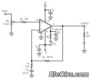
This is a simple circuit of a low-power voltage regulator reference. This circuit can produce a stable voltage reference. The low-power voltage regulator reference circuit is designed to provide a consistent output voltage, which is crucial for various electronic applications...
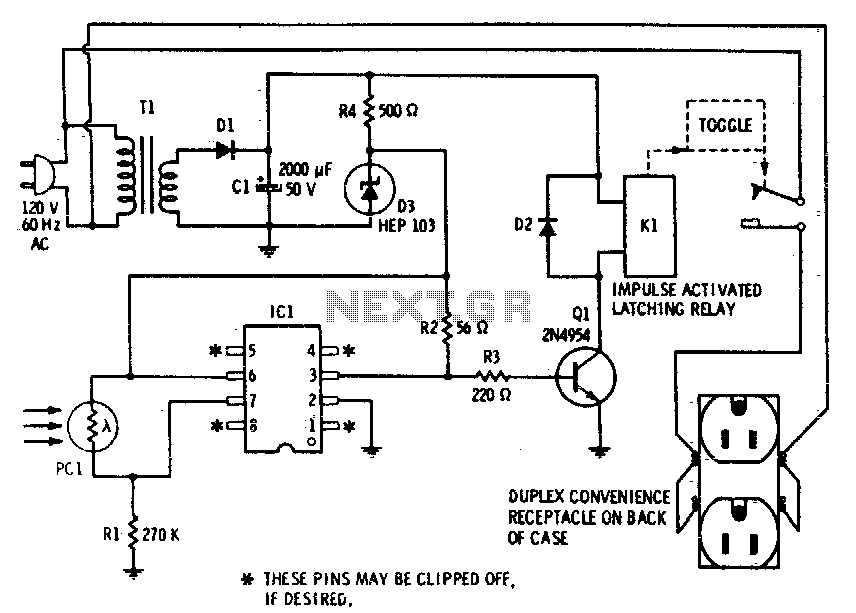
This device enables remote control of AC-powered appliances by utilizing the beam of a flashlight as a triggering mechanism. A key feature of this gadget is its memory function; activating it once supplies power to the device, and it...
A center tap transformer is required. For instance, to obtain a 12V output, connect J1 to the 15V transformer output, J2 to 0V, and J3 to another 15V. A center tap transformer is a specialized transformer that has a secondary...
The SheevaPlug is known to have a suboptimal power supply, particularly affecting users in the UK operating at 240VAC. Additionally, heavy loads on the USB can cause issues, especially when connecting an external mechanical disk drive. This project aims...
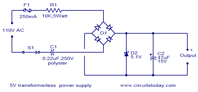
The circuit diagram illustrates a 5V transformerless power supply utilizing minimal components. The operation of this circuit is straightforward. Resistor R1 serves as a current limiter, while bridge D1 rectifies the mains voltage. The Zener diode regulates the output...
The LM3886 high-performance audio power amplifier circuit schematic is a crucial component in sound reproduction within audio systems. This audio power amplifier utilizes the LM3886 integrated circuit to enhance sound quality and output. The LM3886 is a high-performance audio power...