
5V transformer less power supply
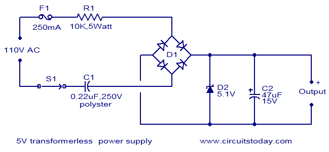
This transformerless power supply circuit is designed for low-power applications where isolation from the mains voltage is not a primary concern. The key components include a resistor (R1), a bridge rectifier (D1), a Zener diode, and a filter capacitor (C2).
Resistor R1 limits the current flowing through the circuit, ensuring that the downstream components are not subjected to excessive current levels. The choice of resistance value is critical, as it must be calculated based on the expected load current and the input voltage to maintain safe operating conditions.
The bridge rectifier (D1) consists of four diodes arranged in a configuration that allows AC mains voltage to be converted into pulsating DC voltage. This rectification process is essential for powering DC loads. The output of the rectifier is characterized by a ripple voltage, which can be smoothed out by the filter capacitor (C2).
The Zener diode is employed to regulate the output voltage to a precise 5V DC. It operates in reverse breakdown mode, maintaining a constant voltage across its terminals as long as the current remains within specified limits. This regulation is crucial for applications requiring stable voltage levels.
Capacitor C2 plays a vital role in filtering the rectified output. It charges during the peak voltage periods and discharges during the lower voltage intervals, thus reducing the ripple voltage and providing a more stable DC output. The capacitance value must be selected based on the load requirements and the level of acceptable ripple.
Overall, this circuit provides a compact and efficient solution for converting AC mains voltage to a low-voltage DC supply, suitable for powering small electronic devices. However, it is essential to consider safety and compliance with electrical standards, particularly when working with mains voltage.Here is the circuit diagram of a 5V transformer less power supply using minimum components. The working of this circuit is quite simple. Resistor R1 does the job of current limiting and bridge D1 rectifies the mains voltage. The Zener diode regulates the rectifier output to obtain a steady 5V DC and capacitor C2 acts as a filter. 🔗 External reference
Related Circuits
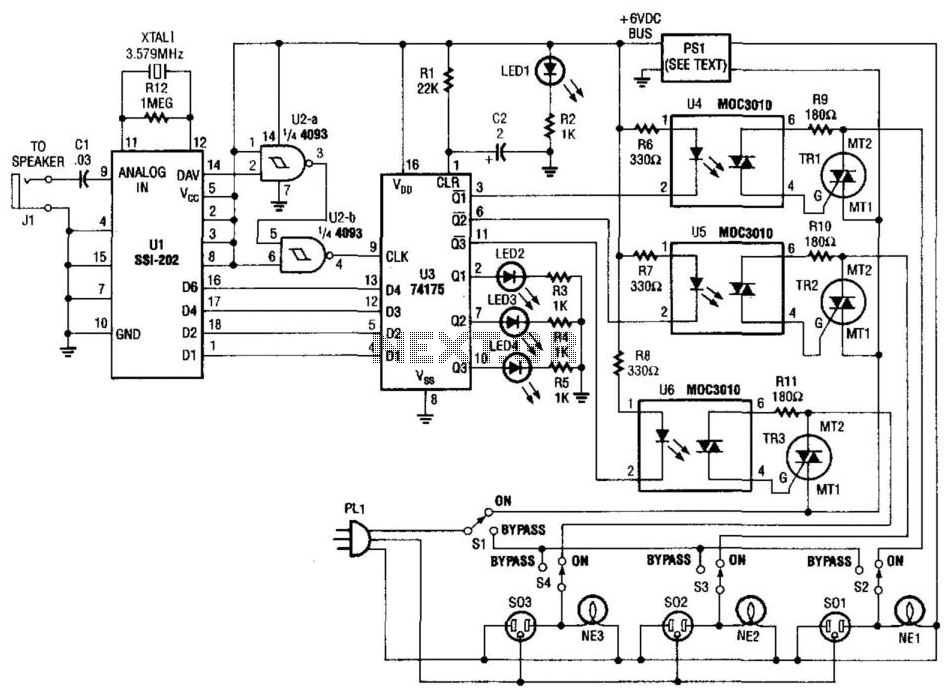
Tones from the DTMF on the telephone line are detected by U1. When a valid tone is received, pin 14 (D More: AV) of U1 produces a positive pulse that is used to drive NAND gates U2A and U2B,...
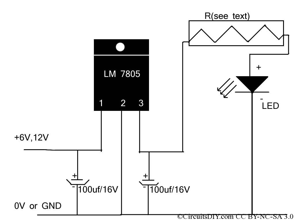
If the reader arrived here via Google, they may have encountered other circuits for high-power LED driving that include many components such as inductors, operational amplifiers, various regulator ICs, transistor feedback networks, and microcontrollers. While those circuits tend to...
The lack of compensation facilitates the processes of development and testing. The figure of 6 billion frequently appears as the estimated number of cell phones in use globally. Published estimates indicate an average. The discussion of compensation in electronic circuits...
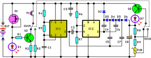
FET Q1 functions as a constant current generator, providing biasing for LED D1 and the base of Q2. This configuration ensures that D1 emits light at a consistent intensity, regardless of the battery voltage, which ranges from 3 to...
The LTC1046 is a 50mA monolithic CMOS switched capacitor voltage converter. It serves as a replacement for the ICL7660/LTC1044 in 5V applications where higher output current is required. This device is optimized for high current capability with input voltages...
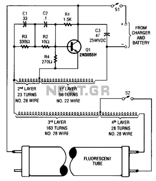
A 2N3055 oscillator (Q1) drives a homemade transformer, wound on a Vk ferrite rod. S2 is used as a filament switch and can be eliminated if desired. A 20-W fluorescent tube is recommended. The supply voltage is 12 V. The...