
power supply circuit
The circuit design incorporates a DC-DC converter with a wide input voltage range, ensuring compatibility with both the laptop power adapter and the lead-acid battery. The LTC4355 ideal diode controller is crucial for optimizing power management, enhancing efficiency, and providing fault detection capabilities. The use of MOSFETs instead of traditional diodes significantly reduces power loss, which is essential for maintaining system efficiency, especially under load conditions. The integration of these components creates a robust power supply solution designed to operate reliably in environments with fluctuating power availability, such as during winter storms that may disrupt electrical service. This approach not only ensures stable operation of the SheevaPlug and connected devices but also maximizes the use of available power resources, enhancing overall system performance and reliability.The SheevaPlug is reputed to have a marginal power supply. It seems to be more of an issue for the people in the UK running at 240VAC, and it also seems to be a problem to load the USB too heavily, as happens if you want to add an external mechanical disk drive. Add to that, the fact that I live in a part of the world where the power is pretty unr eliable in the winter. Storms knock down trees and they take the power lines with them. This project attempts to kill three birds with one stone: The premise of the circuit is simple. The SheevaPlug, USB hub, and laptop hard drive are all designed to operate on 5VDC. The circuit utilizes a DC-DC converter to provide +5VDC for the whole system. The DC-DC converter is designed to take input power in the range of 11-24VDC and convert it to a constant 5VDC output. The only bit of trickiness is to arrange for two separate sources of power to feed the DC-DC converter.
The main source comes from 120VAC house wiring through a standard laptop power adaptor. The backup source is from a 12V lead-acid battery. The laptop charger was chosen for easy availability, efficiency, small physical size, and a voltage output of at least 18 VDC. I got a replacement charger for an HP Mini 1000/1100 netbook. It is a 30W adaptor that puts out 19VDC at 1. 6A. It uses a 4. 0mm connector with a 1. 7mm center post, where GND is on the barrel, and V+ is on the center pin. I got a replacement HP Mini 1000 adaptor on eBay for under $10, shipping included. The battery backup power arrives in the form of 12VDC from a lead-acid battery. Even with a charger attached, the voltage across the battery is less than 18 VDC. I will be using a high-quality charger that does not overcharge the battery. In practical terms, this means that you can leave the battery on the charger permanently without cooking all the water out of it.
My first attempt at the circuit combined the two power sources through a pair of Schottky diodes. That is simple, cheap, and works. The problem is that diodes are kind of power inefficient at low voltages. The Schottky diodes drop about 0. 5V across them. The Sheevaplug plus disk draws about 8W at 5V. Using a 12V supply, and assuming an efficiency of 80% for an average DC-DC converter, one can calculate that 0. 8A would be going through the diode. Running 0. 8A through a Schottky diode with a drop of 0. 5V would be 0. 4W of power dissipated just in the diode. That`s a fair inefficiency when you consider that the idle power on my hard disk is also 0. 4W. In the interests of not throwing that 0. 4W of power on the floor, I discovered that these days, you can buy what are called "Ideal Diodes". They are actually a controller IC that drives a MOSFET in a fashion that makes the resulting circuit act like a diode, but without the voltage drop imposed by normal diodes.
The FETs I chose were IRF7469 N-channel MOSFETs, with a 17 milliohm resistance. That means that with same 0. 8A current going through the FET to the DC-DC converter, the power dissipated in the FET itself would be (0. 8A2 *. 017 Ohm) or 0. 011 Watts, or about 1/40th of the power loss in the Schottky diode approach. The new controller circuit uses an LTC4355 controller to combine the power inputs of the two power sources.
The controller can detect all kinds of faults in the system, like undervoltage on the inputs, blown fuses, or faults in the MOSFET drivers themselves. The net result is that the two power sources are combined through the ideal diode controller ASIC. In really simple terms, what this means is that whichever power source has the highest voltage will supply the power to the DC-DC converter.
We purposely choose the voltage output on the laptop power adaptor to be greater than the highest voltage you would see on the battery, even when the battery was charging. This means that the laptop power adaptor will be supplying all the power to the system as long as it is powered.
🔗 External reference
Related Circuits
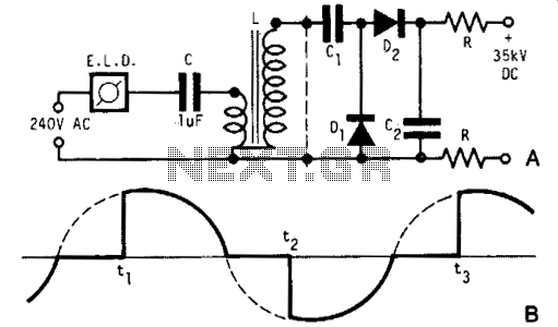
A light dimmer, a 1 µF capacitor, and a 12 V car ignition coil form a simple line-powered high-voltage generator. The current in the dimmer is illustrated in Fig. B. During the time intervals tp to t2, determined by...

The low-cost and compact circuit presented here serves as a highly power-saving flashing LED indicator. While most LEDs typically fail to operate below 2 volts, with a forward voltage of at least 1.6 volts, this flasher can function using...

The circuit includes a K-type thermocouple cold junction compensation circuit, a precision 5.000V reference voltage source, and an OP113 operational amplifier. It is capable of measuring temperatures ranging from 0°C to 100°C with a resolution of 0.02°C. The OP113...

The schematic illustrates the subwoofer amplifier stage, specifically the pre-amplifier circuit and the signal processing circuit. Notably, it features two LM3886 power ICs from the American company NS, which facilitate BTL (Bridge-Tied Load) speaker operation at an 8-ohm impedance...
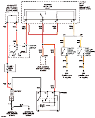
This circuit below shows an electrical circuit applicable for the Audi A4 Quattro 2004 model year. Component: Transmission, Anti-lock Brakes Circuit. The electrical circuit for the Audi A4 Quattro 2004 model year encompasses critical components such as the transmission system...

An NE555 timer integrated circuit (IC) configured in a specific manner can identify the absence of a pulse or an unusually long duration between two successive pulses in a pulse train. Such circuits are applicable for detecting the intermittent...
Warning: include(partials/cookie-banner.php): Failed to open stream: Permission denied in /var/www/html/nextgr/view-circuit.php on line 713
Warning: include(): Failed opening 'partials/cookie-banner.php' for inclusion (include_path='.:/usr/share/php') in /var/www/html/nextgr/view-circuit.php on line 713