
5V Regulated Power Supply
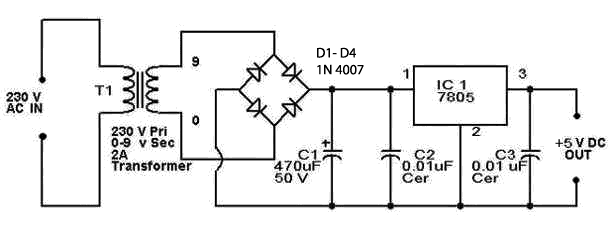
The 5V regulated power supply circuit is designed to provide a stable output voltage of 5 volts, which is essential for powering various electronic devices and circuits. This type of power supply typically utilizes a transformer, a rectifier, and a voltage regulator to ensure that the output voltage remains constant, even when the input voltage or load conditions change.
The circuit begins with an AC power source, which is connected to a step-down transformer. The transformer reduces the high AC voltage to a lower AC voltage suitable for the application. The output of the transformer is then fed into a rectifier, which can be a full-wave or half-wave rectifier, depending on design requirements. The rectifier converts the AC voltage into pulsating DC voltage.
Following the rectification process, the pulsating DC voltage is smoothed using a filter capacitor. This capacitor charges during the peaks of the rectified voltage and discharges during the troughs, effectively reducing the ripple voltage and providing a more stable DC output.
To achieve the desired output voltage of 5V, a linear voltage regulator, such as the 7805, is employed. The 7805 regulator takes the smoothed DC voltage and outputs a regulated 5V, ensuring that fluctuations in the input voltage or load do not affect the output voltage. Additional capacitors may be placed at the input and output of the regulator to improve transient response and stability.
This power supply circuit is widely used in various applications, including microcontroller circuits, sensor systems, and communication devices, where a reliable 5V supply is crucial for proper operation. Proper heat dissipation measures should also be considered, as linear regulators can generate heat when there is a significant voltage drop across them, especially under higher load conditions.5v regulated power supply circuit, 5v power supply circuit, regulated power supply circuit diagram.. 🔗 External reference
Related Circuits
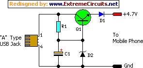
This simple circuit provides a regulated output of 4.7 volts for charging a mobile phone. A USB outlet supplies 5 volts DC at 100mA, which is adequate for slow charging of mobile phones. Most mobile phone batteries are rated...
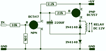
This circuit allows a 12v relay to operate on a 6v or 9v supply. Most 12v relays need about 12v to "pull-in" but will "hold" on about 6v. The 220u charges via the 2k2 and bottom diode. When an...
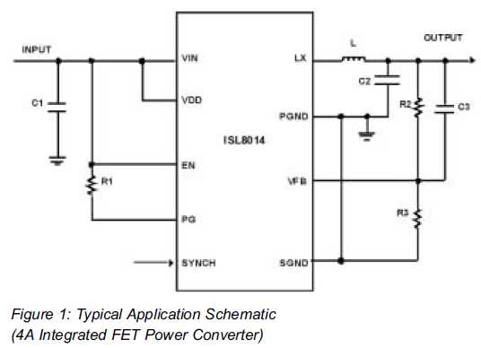
Utilizing Integrated Switching Regulators in Power Supply Design Engineers often find themselves pondering where to begin when designing power supplies. Key decisions must be made regarding... Integrated switching regulators are critical components in modern power supply design, offering efficient voltage...
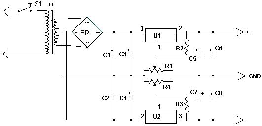
This dual polarity power supply is simple to construct, requires minimal components, and is adjustable from 0 to 15 volts. It is suitable for powering operational amplifier circuits as well as other circuits that necessitate a dual supply voltage....
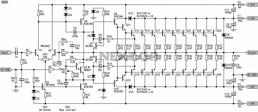
A 1500W power amplifier circuit design diagram created by Rod Elliott. The circuit utilizes 10 pairs of power transistors, specifically MJ15024 and MJ15025, or alternatively MJ21193 and MJ21194. The 1500W power amplifier circuit is designed for high-performance audio applications, providing...
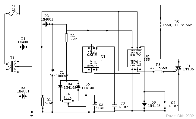
The circuit is built around two 555 timer ICs, U1 and U2. U1 is configured as a variable duty cycle oscillator with a constant time period of approximately 0.1 seconds. The duty cycle can be adjusted from 0 to...