
Power Supply Design Made Easy
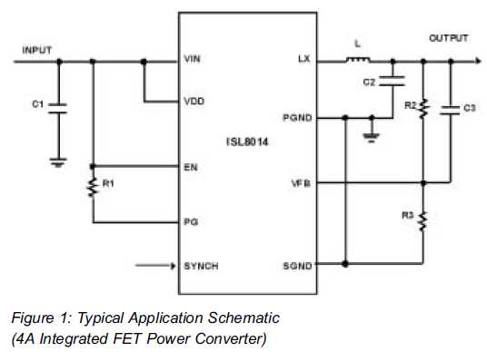
Integrated switching regulators are critical components in modern power supply design, offering efficient voltage conversion and regulation. These devices utilize a method of switching to control the output voltage, significantly reducing energy losses compared to linear regulators. The design process begins with determining the input voltage range and the desired output voltage and current specifications.
Engineers must consider the switching frequency, which impacts the size of passive components such as inductors and capacitors. Higher frequencies allow for smaller components but may introduce challenges such as increased electromagnetic interference (EMI) and reduced efficiency due to switching losses.
In selecting an integrated switching regulator, it is essential to evaluate the control topology—voltage mode or current mode—each offering different benefits in terms of transient response and stability. Additionally, the choice of external components, including inductors and capacitors, must align with the regulator's specifications to ensure optimal performance.
Thermal management is another critical aspect, as switching regulators can generate heat during operation. Proper heat sinking or thermal pads may be necessary to maintain component reliability. Furthermore, the layout of the PCB plays a significant role in minimizing parasitic inductance and capacitance, which can affect the regulator's performance.
Overall, the integration of switching regulators in power supply design enhances efficiency and allows for compact designs, making them a preferred choice in various applications, from consumer electronics to industrial equipment.Using Integrated Switching Regulators When it came to power supply design, most Engineers would scratch their head thinking, œWhere do I start? Decision must be decided concerning.. 🔗 External reference
Related Circuits
Simple and low cost. The optimal supply voltage is around 50V, but this amp works from 30 to 60V. The maximal input voltage is around 0.8 - 1V. As you can see, in this design the components have a...
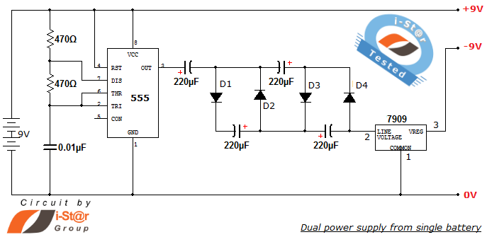
How to create a dual power supply unit using a single battery for laboratory purposes. Dual voltage power supplies are particularly needed for operational amplifier experiments and some instrumentation amplifiers. Additionally, certain low-power audio preamplifiers also require dual voltage...
This circuit was designed and manufactured in the 1980s. Since then, it has operated without issues. There are no significant constructional challenges, aside from the usual considerations: ensuring the appropriate power supply voltage, selecting a suitable heatsink, and properly...
This is an efficient four-stage stabilized power supply unit designed for testing electronic circuits. It delivers well-regulated and stabilized outputs, which are crucial for achieving accurate results in most electronic applications. The circuit features an audio-visual indication system that...
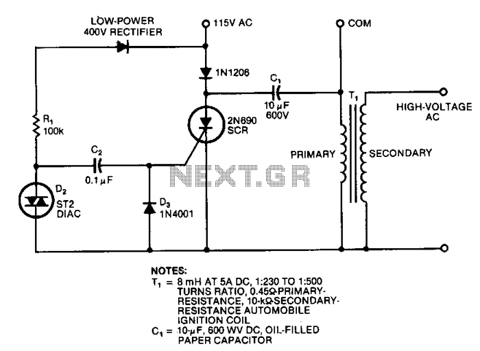
This circuit generates high-voltage pulses using an inexpensive auto ignition coil. By adding a rectifier to the output, the circuit produces high-voltage direct current (DC). The input to the circuit is 115 Vac. During the positive half cycle of...

This article was originally published in a slightly modified form in the QST magazine, December 1998 and January 1999, and in the Radio Amateur's Handbook, 1999. Visit the American Radio Relay League for information on these publications and a...
Warning: include(partials/cookie-banner.php): Failed to open stream: Permission denied in /var/www/html/nextgr/view-circuit.php on line 713
Warning: include(): Failed opening 'partials/cookie-banner.php' for inclusion (include_path='.:/usr/share/php') in /var/www/html/nextgr/view-circuit.php on line 713