
6 Channel Auto Reverse Sequential Disco Running Lightss
The circuit begins with a power supply that converts 230 V AC to a stable +5 V DC output, ensuring that the subsequent components operate within their required voltage specifications. This DC supply is essential for powering the pulse generator and the integrated circuits involved in the operation.
The pulse generator, implemented using an IC 555, operates in astable mode to produce a continuous stream of clock pulses. The frequency of these pulses can be adjusted by selecting appropriate resistor and capacitor values in the circuit, allowing for flexibility in the operation of the entire system. The generated clock pulses are fed into an IC 4017, which functions as a decade counter. The IC 4017 counts the incoming pulses and provides an output signal after every 10 pulses, effectively creating a controlled sequence for the subsequent components.
The output from the IC 4017 is used to drive a series of transistors configured as switches. These transistors are crucial for controlling the triacs, which are semiconductor devices that allow current to flow in both directions. When the transistors are activated by the output from the counter, they trigger the corresponding triacs, enabling them to conduct and supply power to the connected load.
In this circuit, decorative bulbs are utilized as the load for each triac. The design allows for sequential activation of the bulbs, with the triacs turning them ON and OFF in a programmed sequence. This not only creates an appealing visual effect but also demonstrates the capability of the circuit to control AC loads using low-voltage DC signals.
The operation of the circuit can be enhanced by incorporating additional features such as variable pulse frequency, dimming capabilities, or even remote control functionalities, depending on the application requirements. Overall, this schematic effectively showcases the integration of various electronic components to achieve a specific control mechanism for AC loads using a simple yet effective counting and triggering system.From 230 V AC a DC supply of + 5 V is obtained. The power supply is given to the other blocks. The pulse generator at a particular frequency generates the clock pulses. The clock pulses are counted by a counter and gives output after every 10 pulses. The counter drives the transistors, which form the triac firing circuit. The transistors fire thetriacs and they provide sufficient current to the load. Decorative bulbs are connected as load for each triac. The bulbs are sequentially turned ON and OFF in forward and reverse way. The IC 555 works as the pulse generator and feeds the clock pulses to IC 4017. IC 4017 is the heart of this circuit. It works as a counter and gives the output after every 10 pulses. It drives the transistors, which in turn fire the triacs. The triac provides sufficient current to the load. 🔗 External reference
Related Circuits
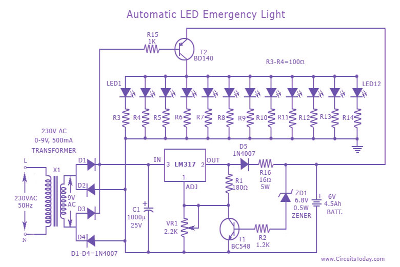
The charging circuit automatically stops when the battery is fully charged, allowing the emergency light to remain connected to the AC mains overnight without concern. The circuit consists of two main sections: the inverter and the charger. The inverter...

This 4-channel commutator utilizes the 2N4091 to achieve a low channel ON resistance (approximately 30 ohms) and minimal OFF current leakage. The DM7800 voltage translator is a monolithic device that provides gate drive voltages ranging from 10V to 20V...
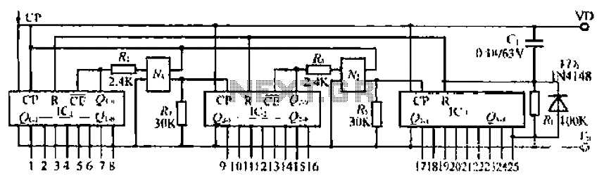
The CD4017B input signal is applied to the CP triggering pin. A pulse signal is sent through the IC, resulting in a straight-through output signal. The coupling device is used to control the input signal. When the power is...
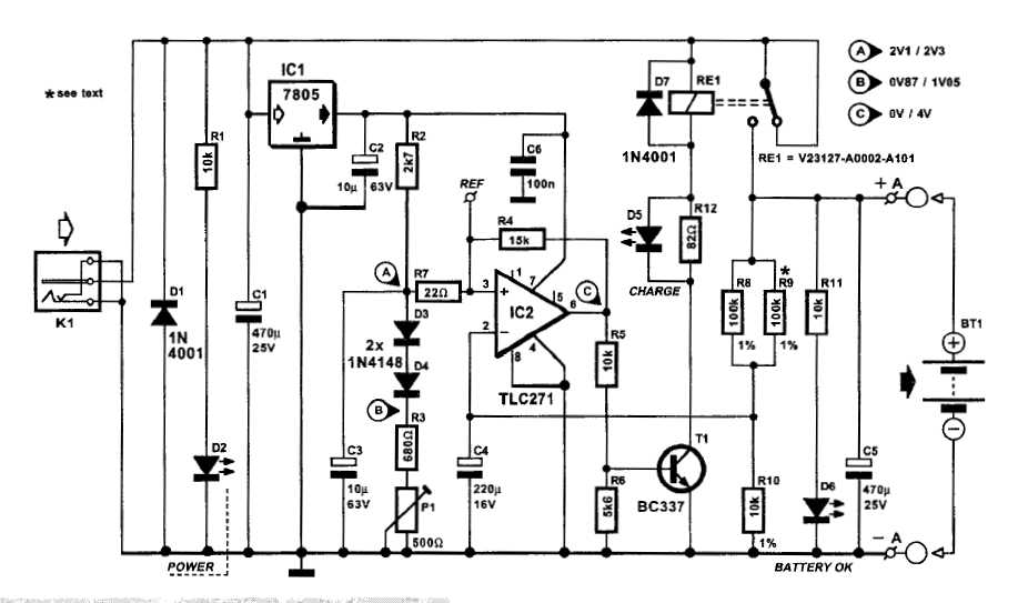
An automatic battery charger initiates the charging process when the battery voltage falls below a specified threshold and ceases charging once the voltage exceeds a predetermined maximum value. The setup is straightforward; simply connect two alligator clips to the...
This is a cost-effective and straightforward emergency light circuit developed for CircuitsToday. It is an automatic emergency lamp with daylight sensing capabilities, meaning it detects darkness and turns on automatically, while also sensing daylight to turn off. The circuit...
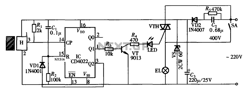
The circuit illustrated in the figure depicts an automatic bathroom light switch system. When the door is opened, the light is activated, illuminating the space. Conversely, when the door is opened again, the light turns off. The circuit comprises...