
A multi-channel pulse distributor circuit
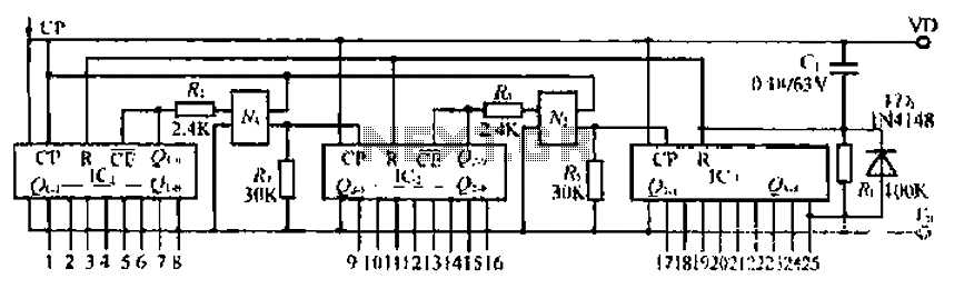
The CD4017B is a decade counter IC commonly used in digital circuits for counting applications. It features a series of outputs that activate sequentially with each pulse applied to the clock input (CP). The functioning of the CD4017B begins with the application of an input signal to the CP pin, which triggers the counting action.
In this configuration, a photoelectric coupling device is employed to isolate the input signal from the rest of the circuit. This isolation is crucial in applications where the input signal may have noise or varying voltage levels that could interfere with the operation of the CD4017B. The photoelectric coupler ensures that only the desired signal is transmitted to the IC, thus enhancing reliability and preventing damage to sensitive components.
When the power supply is activated, a capacitor is also introduced into the circuit, which can serve multiple purposes. It may be used for debouncing the input signal to eliminate false triggering caused by noise or to provide a delay in the signal, allowing for a more stable operation of the counter. The capacitor charges and discharges in response to the input signal, influencing the timing characteristics of the circuit.
Overall, the integration of the CD4017B with a photoelectric coupling device and a capacitor provides a robust solution for counting applications while ensuring signal integrity and stability. This configuration is suitable for various electronic projects, including timers, event counters, and digital displays. CD4017B input signal is applied where CP triggering end, I lost A ~ 3HCD4017B pulse signal is liter inline J. IC Icl a straight-through output signal hill, iq is through Nortel coupling device ~. After the input signal control. After mentioning IC input signal A photoelectric coupling device M after control. When the power is turned on, the capacitor
Related Circuits
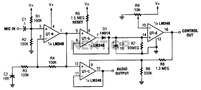
In specific applications, such as transmitters or other communications and control systems, this circuit is designed to be beneficial. It provides both audio output and DC control outputs. Additionally, R9 establishes the control threshold. The circuit in question is versatile...
The primary goal of this project is to utilize 555 timers to detect motion in the surrounding environment. The output of this circuit will activate an LED and produce an audible sound similar to an alarm. The circuit design employs...
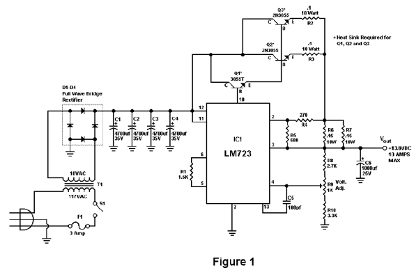
The circuit is designed to deliver a surge current of 12 amps, offering performance that meets or surpasses that of typical commercial units. Additionally, it incorporates a current limiting feature, providing a level of reliability that is superior to...
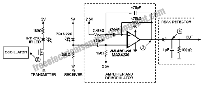
The following circuit illustrates an Infrared Proximity Sensor Circuit Diagram. This circuit is based on the MAX4230 integrated circuit. Features include a 10 kHz oscillator. The Infrared Proximity Sensor Circuit utilizing the MAX4230 integrated circuit is designed to detect the...
A touch sensor relaxation oscillator is utilized in the hysteresis lab. In this schematic, the variable capacitor is represented by a person's finger and a touch plate made from aluminum foil and packing tape. Code was developed for the...
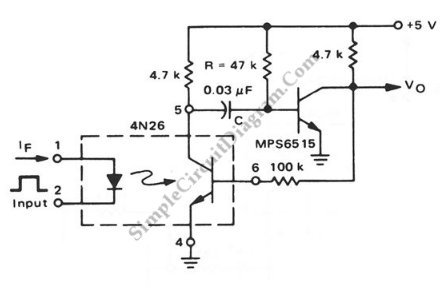
This is a pulse stretcher circuit utilizing an optocoupler. The circuit employs a 4N26 optocoupler in conjunction with a standard one-shot circuitry. The pulse stretcher circuit is designed to elongate the duration of an incoming pulse signal, which is particularly...
Warning: include(partials/cookie-banner.php): Failed to open stream: Permission denied in /var/www/html/nextgr/view-circuit.php on line 713
Warning: include(): Failed opening 'partials/cookie-banner.php' for inclusion (include_path='.:/usr/share/php') in /var/www/html/nextgr/view-circuit.php on line 713