
6 to 35kV substation cable entry into the segment of Lightning b
The 6-35kV cable line substation is designed to manage high-voltage electrical distribution while ensuring safety against lightning strikes. The lightning protection system is a critical component that safeguards the integrity of the electrical infrastructure. It involves the installation of surge arresters and grounding systems that divert excessive voltage away from sensitive equipment and structures.
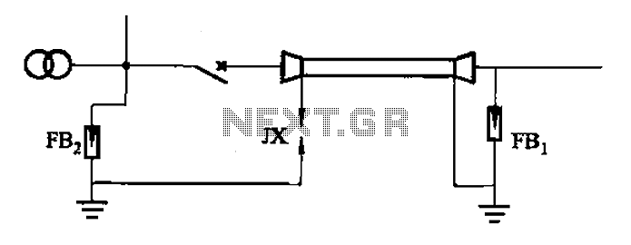
In the case of single-core cables, particular attention must be paid to the termination of the metal sheath. This metal sheath serves as a protective barrier against electromagnetic interference and physical damage. The proper grounding of this sheath is essential to prevent potential electrical hazards. The ground clearance, denoted as JX, must comply with local regulations and standards to ensure adequate protection against lightning-induced surges.
The design of the substation should include a detailed schematic that outlines the placement of lightning rods, grounding electrodes, and surge protective devices. The schematic should also indicate the routing of cables, the connection points for grounding, and the specifications for the materials used in the construction of the lightning protection system. Proper implementation of these elements will enhance the reliability and safety of the substation, ensuring uninterrupted service in adverse weather conditions.6-35kV cable line substation, into its line of lightning protection can be Figure (a), the protection of access lines; for single-core cable, the end of the metal sheath shall be subject to the protection of ground clearance JX, as ( b). 6 to 35kV substation cable entry into the segment of Lightning b
Related Circuits
The Sound Blaster MIDI port utilizes two pins from a 15-pin joystick port, which typically serve as redundant +5 volt and ground lines. In the context of the Sound Blaster, these pins are designated as MIDI TXD (Transmit eXternal...
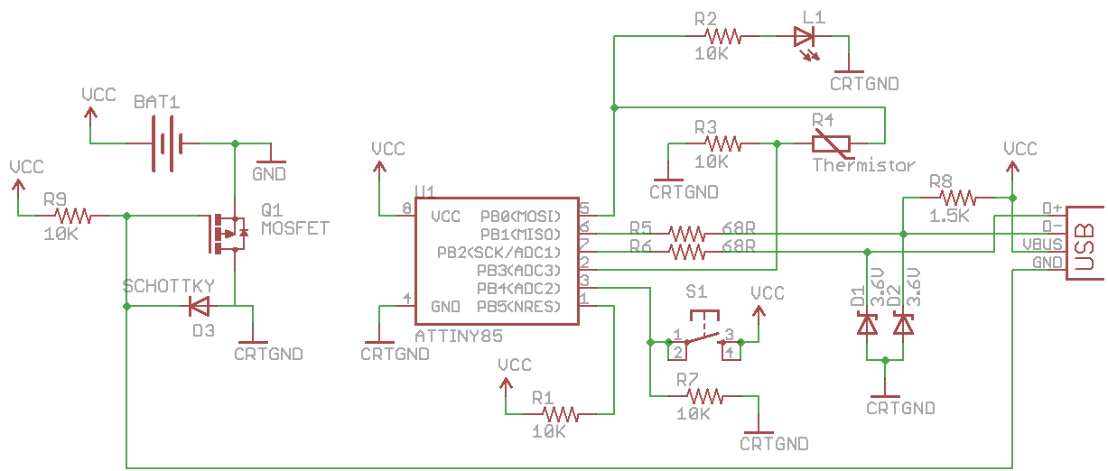
CRTGND is not equivalent to GND; CRTGND connects to the MOSFET drain or Schottky diode. A disadvantage of this circuit is the voltage drop when powered from the USB side due to the diode. The USB voltage can fluctuate...
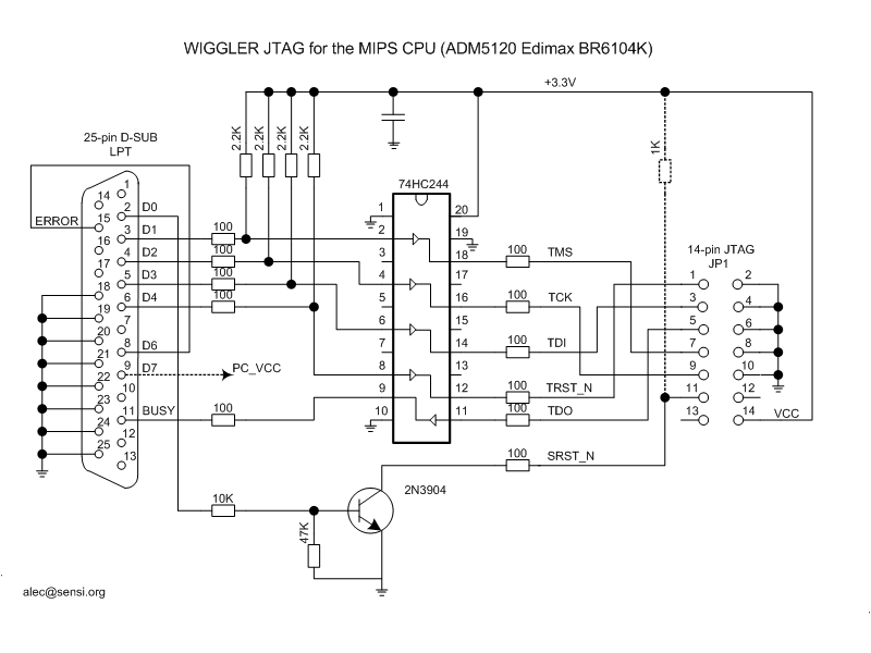
This type of cable is more complex than the unbuffered variant, yet it is still relatively easy to construct. The most commonly used cable in this category is the Wiggler cable, which is commercially available from Macraigor Systems. Priced...
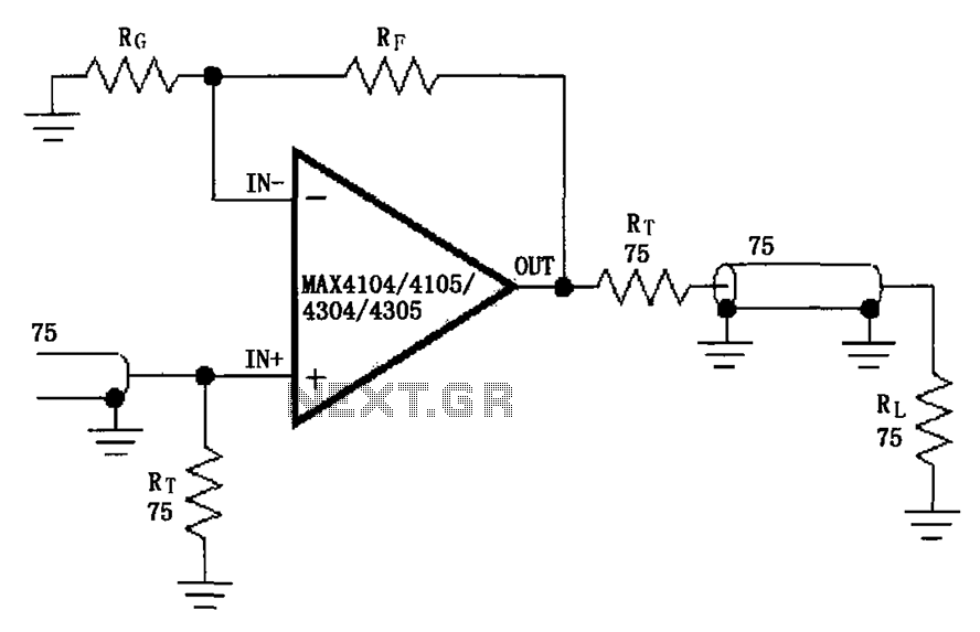
The circuit illustrated in the figure features a MAX4104/4105/4304/4305 video cable driver amplifier. This circuit is designed for use with coaxial transmission lines, optimizing the amplification of video signals to minimize reflections and maximize power transfer. The output impedance...
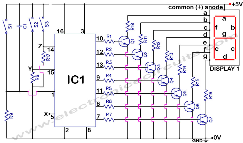
4033 7 Segment Common Anode Display Event Counter Circuit. This circuit can count from 0 to 9 with a reset function and a display test feature. The 4033 7-segment common anode display event counter circuit is designed to count events...
A collection of Kenwood TK-760G-1 transceivers (two-way radios) was programmed to a single channel, with all other features locked. Various programming software for Kenwood was gathered from the internet and local newsgroups, but a programming cable was required. The...