
Implement automatic voltage switching into the SATL
The setup function is designed to change the clock speed from 2MHz to 1MHz by modifying the clock prescaler. The prescaler enable bit is set, followed by the clock division factor set to 16, resulting in a 1MHz operation (16MHz PLL / 16). When USB is connected, data is sent from EEPROM to USB, and the clock speed is increased to 16MHz. Interrupts are disabled during this process, and after the USB transfer is complete, the clock speed is reduced back to 1MHz. The A2D prescale factor is set to 8, ensuring that the A2D conversions operate within the desired frequency range of 50-200 kHz. The prescaler is manually configured at the end of the setup function to maintain compatibility with the USB code, which requires the clock speed to be at 16.5MHz.
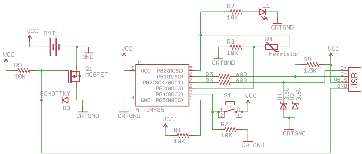
This circuit design effectively manages voltage levels and clock speeds to ensure reliable performance of the ATtiny85 microcontroller in various operational scenarios. The use of a Schottky diode minimizes voltage drop, and the clock speed management allows for safe operation when powered by different sources.CRTGND is not the same as GND, CRTGND connects to the mostfet drain/schottky diode. There is a downside to this circuit which is that there is a voltage drop when running from the USB side due to the diode. The USB voltage can vary between 4. 75V to 5. 25V and the good news is that our ATtiny85 can run fine at 16. 5MHz whilst at 4. 0V. If the USB voltage was really 4. 75V, we would just make it to 4. 05V but we want the best possible voltage even if it was 4. 75V. Instead of using just a standard diode we`ll use a schottky diode which can provide a lower voltage drop of 0. 3V instead of the 0. 7V from standard diodes. We could just wire it all up and run it but we have a problem. If we insert the battery, by default we are running at 16MHz (using the PLL clock) which is outside of the safe frequency range of 3V when powered by the battery.
Before we go any further please take a look at my video called Change the ATtiny85 clock speed on the fly which will give you an idea of how we can change the clock speed using the clock prescaler. What we`ll need to do is somehow have the ATtiny85 reduce it`s clock speed when powered on. When the ATtiny85 comes out of the factory it`s clock speed is 1MHz even though it uses the internal 8MHz oscillator.
It does this by setting a fuse bit (CKDIV8) to divide the clock by 8 which gives us the 1MHz. So let`s just set this CKDIV8 fuse bit on again (we turned it off when we were playing around with V-USB and set our clock to PLL) which will make it run at 2MHz (16MHz / 8 ) when power is applied to it. After it`s powered on, we could then reduce the clock even more to give our desired clock of 1MHz and just ramp back up to 16MHz when we detect that the USB is connected.
void setup(void) { // Change 2MHz to 1 MHz by changing clock prescaler to 16 CLKPR = (1<
c, let`s add the code to change to 16MHz when USB is detected and then change back to 1MHz after the USB transfer is complete; we need to disable interrupts before doing so and then re-enable them. // Set A2D prescale factor to 8 // 1 MHz / 8 = 125 KHz, inside the desired 50-200 KHz range. sbi(ADCSRA, ADPS1); sbi(ADCSRA, ADPS0); // Enable A2D conversions sbi(ADCSRA, ADEN); Previously the A2D prescaler was set by checking the F_CPU but since the definition would be 16.
5MHz it would result in a prescaler of 128 which won`t work when we are at 1MHz (as 1MHz / 128 = 0. 007 KHz) so let`s set the prescaler manually ourselves at the end of the setup function. The reason we don`t touch F_CPU is because the it`s needed to be at 16. 5MHz for USB code to work. Because we changed the clock speed this means that any c 🔗 External reference
Related Circuits
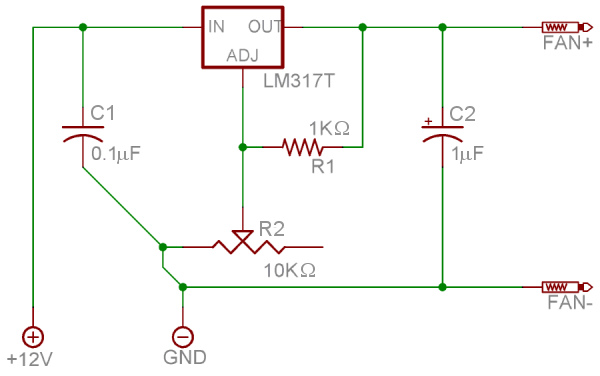
The LM317T is a widely used positive voltage regulator, forming the basis for many laboratory power supplies and other equipment. It can output a voltage ranging from 1.25V to 35V by adjusting the resistance between its adjustment pin and...
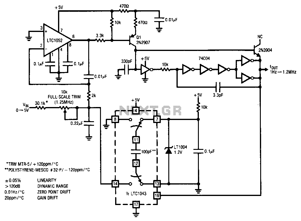
This stabilized voltage-to-frequency converter operates within a range of 1 Hz to 1.25 MHz, featuring a linearity of 0.05% and a typical temperature coefficient of 20 ppm/°C. The circuit is powered by a single 5-V supply. It employs a...
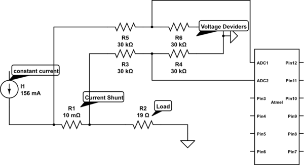
Measure current on a constant current source (LM317). Since a 3.3V chip is being used, a voltage divider is also required for reading the current. Will this circuit function correctly, or will it cause issues by attempting to increase...
To achieve optimal audio reproduction across various listening levels, it is essential to adjust tone control settings to accommodate the known characteristics of human hearing. Human ear sensitivity changes in a non-linear fashion throughout the audible frequency range, as...
This circuit generates a constant current, constant voltage switched-mode power supply (SMPS). It is designed to efficiently charge a battery using a constant current, constant voltage approach. The circuit operates as a constant current, constant voltage SMPS, which is crucial...
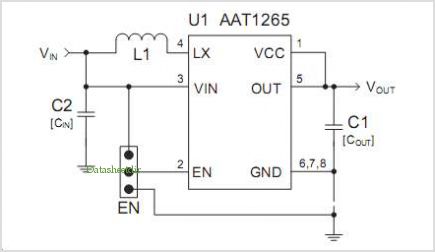
The AAT1275 evaluation board serves as a platform for testing and evaluating the AAT1275 switching boost converter equipped with a USB power switch. This evaluation board showcases the recommended size and placement of external components to achieve 5V output...