
4033 7 Segment Common Anode Display Counter

The 4033 7-segment common anode display event counter circuit is designed to count events in a range from 0 to 9. It utilizes a 4033 integrated circuit, which is a decade counter that can drive a common anode 7-segment display. The circuit is capable of resetting the count and includes a display test feature to ensure proper operation of the display segments.
In this circuit, the 4033 IC is connected to the 7-segment display such that each output pin corresponds to a segment of the display. The common anode configuration means that the anodes of the display segments are connected to a positive voltage supply, while the cathodes are driven low to illuminate the segments. The counting operation is initiated by applying a clock signal to the clock input of the 4033. Each pulse of the clock increments the counter by one, and the corresponding output pins are activated to display the current count on the 7-segment display.
A reset button is typically included in the design, connected to the reset pin of the 4033. Pressing this button will reset the counter back to zero, allowing for a new counting session to begin. The display test feature is implemented by connecting a test button to the 4033, which, when pressed, activates all segments of the display simultaneously. This allows for verification that each segment is functioning correctly.
Power supply requirements for this circuit usually involve a standard voltage of 5V, which is suitable for the 4033 IC and the 7-segment display. Proper decoupling capacitors should be included near the power supply pins of the IC to filter out noise and ensure stable operation.
Overall, the 4033 7-segment common anode display event counter circuit is a straightforward yet effective solution for counting applications, providing visual feedback through the display and allowing for easy reset and testing functionalities.4033 7 Segment Common Anode Display Event Counter Circuit This circuit can count 0 to 9 with reset and display test.. 🔗 External reference
Related Circuits
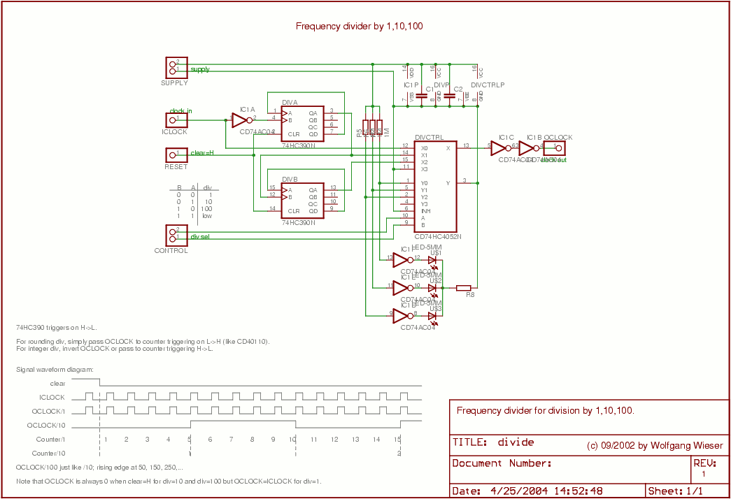
The divider design is straightforward. Users can select a division factor of 1, 10, or 100, or opt for no output (tied low) through the CONTROL input connected to the analog multiplexer HC4052. The design utilizes AC04 to drive...
This circuit is designed for the selection of alternative sources. It integrates mechanical selection through a rotating switch S1, electronic control of relays RL1 to RL10, and optical indication of the selection via the display DSP1. The circuit operates by...
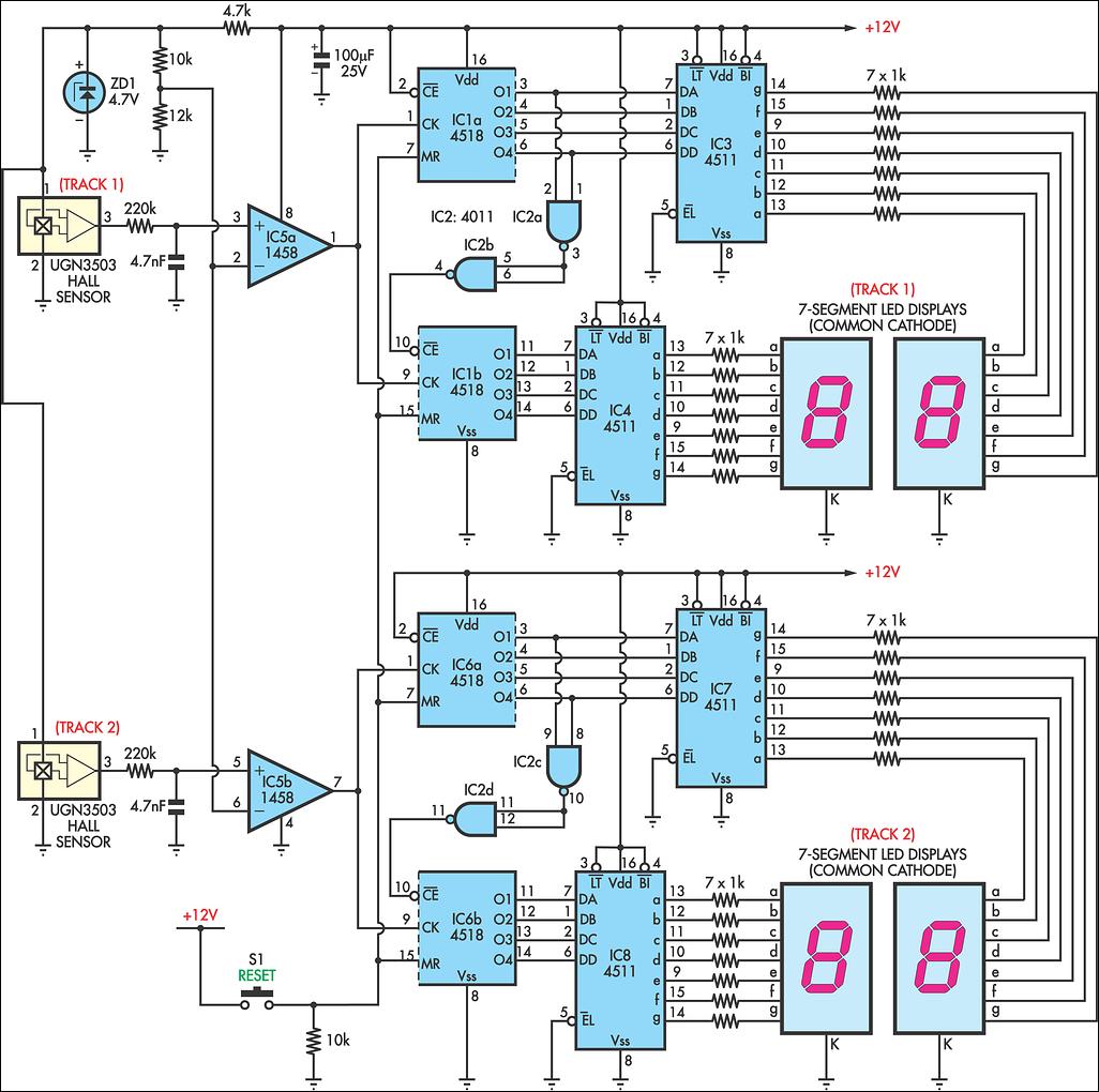
AFX slot car sets are enjoyable, and the experience can be enhanced with a lap counter. This circuit counts from 00 to 99, featuring independent counters for each track. The sensing device utilized is a Hall effect sensor (UGN3503),...
Connecting a LCD display to your personal computer is an easy job. Displaying data from your PC to a LCD can be proven very exciting, so give it a try and build your own today! In this article, we...
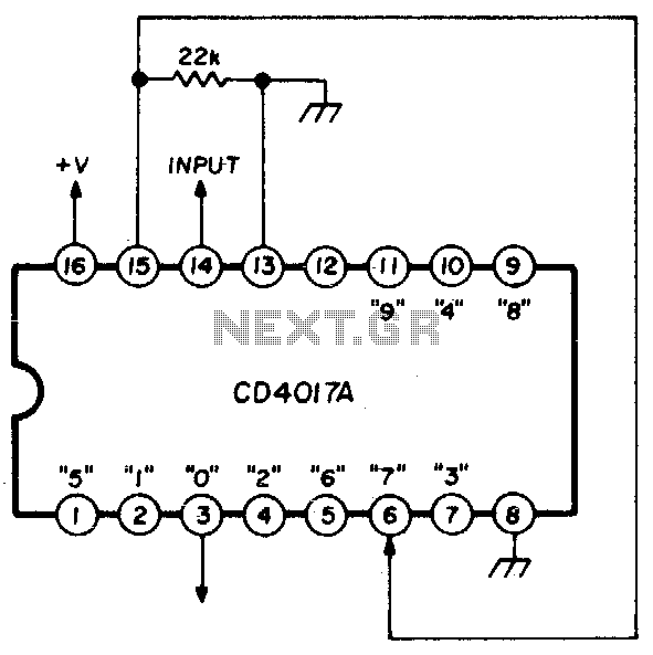
A single connection change allows division by any integer between 2 and 10. The RCA CD4017A Johnson decade counter is configured as a divide-by-7 counter. A resistor is utilized to maintain the reset line in a low state. When...
This circuit is a small digital roulette. It consists of an oscillator IC1, a counter IC2, and transistors Q1-7 that drive the common cathode display DSP1. The power supply typically comes from a 9V battery, but it can also...