
6 Volt Automatic Emergency Light Battery
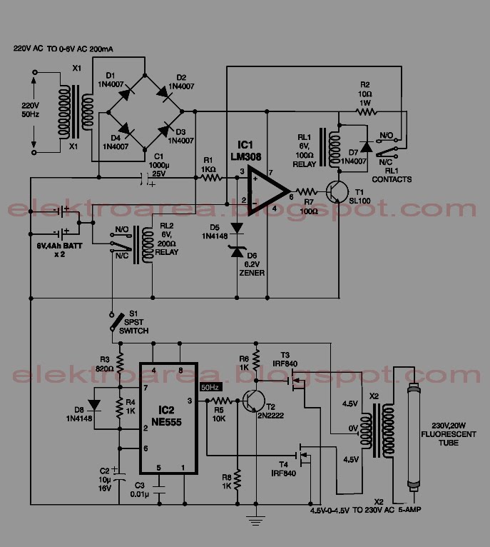
The described circuit functions as a reliable emergency lighting solution, utilizing an integrated circuit (IC) to manage both the charging of the battery and the operation of the inverter. The NE555 timer (IC2) serves as a pulse generator, which is crucial for the operation of the MOSFETs T3 and T4. These MOSFETs are responsible for converting the DC voltage from the battery into the AC voltage needed to power a fluorescent tube during a power outage. The push-pull configuration of the amplifier ensures efficient use of the available power, allowing for a stable output.
The overcharge protection mechanism is vital for maintaining the longevity and safety of the battery. The LM308 comparator (IC1) continuously monitors the battery voltage, ensuring that charging ceases once the voltage exceeds the set threshold of 6.9 volts. This is achieved through a simple voltage divider formed by the zener diode D6 and the 1N4148 diode D5, which provides a stable reference voltage. The relay RL1 acts as a switch that controls the charging circuit, and its operation is critical for preventing damage to the battery due to overcharging.
In addition, the use of suitable heat sinks for the MOSFETs T3 and T4 is necessary to dissipate heat generated during operation, thereby preventing thermal failure. The design allows for flexibility in operation, as the user can disable the emergency light by turning off switch S1, which disconnects the inverter from the battery during mains failure. This feature is particularly useful in scenarios where illumination is not required. Overall, the circuit is designed to provide an efficient and safe emergency lighting solution, ensuring reliable performance during power outages.This circuit is IC controlled emergency light. This series of automatic switching-on of the sunshine on mains failure and battery charger with overcharge protection. When mains is absent, the relay RL2 is in deenergised state, feeding battery offer to the inverter section via its N / C contacts and switch S1.
The inverter section contains IC2 (NE5 55) that is used in a very stable fashion to supply sharp pulses at the rate of 50 Hz for driving the MOSFETs. The output of IC3 is fed to the gate of MOSFET (T4) directly whereas it`s applied to MOSFET (T3) when inversion by gate transistor T2.
so the facility amplifier designed around MOSFETs T3 and T4 functions in push-pull mode. The output across the secondary of transformer X2 can easily drive a 230-volt, 20-watt fluorescent tube. In case light is not needed to be on throughout mains failure, simply flip the switch S1 to off position.
Battery overcharge preventer circuit is constructed around IC1 (LM308). Its non-inverting pin is held at a reference voltage of approximately 6. 9 volts that is obtained using diode D5 (1N4148) and 6. 2-volt zener D6. The inverting pin of IC1 is connected to the positive terminal of battery. so when mains offer is gift, Comparator IC1 output is high, unless battery voltage exceeds 6. 9 volts. therefore the transistor T1 is generally forward biased, that energises relay RL1. in this state the battery remains on charge via the N / O contacts of relays RL1 and current limiting resistor R2. When battery voltage exceeds 6. 9 volts (overcharged condition), IC1 output goes low and gets deenergised relay RL1, and so stops more charging of battery.
MOSFETs T3 and T4 may be mounted on suitable heat sinks. 🔗 External reference
Related Circuits
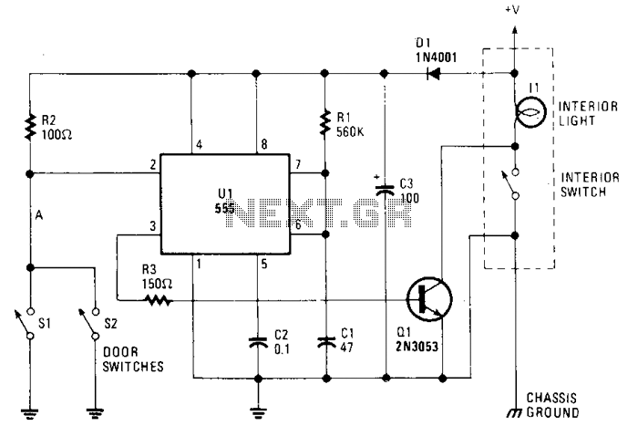
The circuit maintains the courtesy light's illumination for 30 seconds after the door is closed. The lead from the door switch is disconnected and linked to the 555 timer circuit. The 555 timer is configured in monostable mode and...
A voltage-controlled oscillator (VCO) is an electronic signal generator that produces a signal with a variable frequency, which is dependent on an input voltage level. A voltage-controlled oscillator is a fundamental component in various electronic applications, including phase-locked loops (PLLs),...
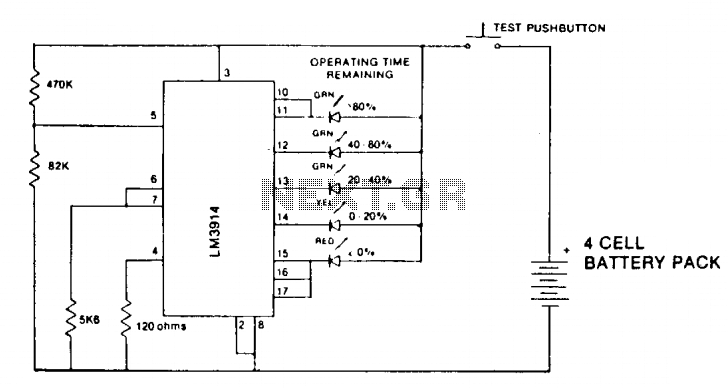
A state-of-charge indication of a sloping-voltage discharge can be utilized as a state-of-charge indicator. A typical voltage comparator circuit that provides a visual indication of the state of charge is presented. Components identified are for a 4-cell input voltage...
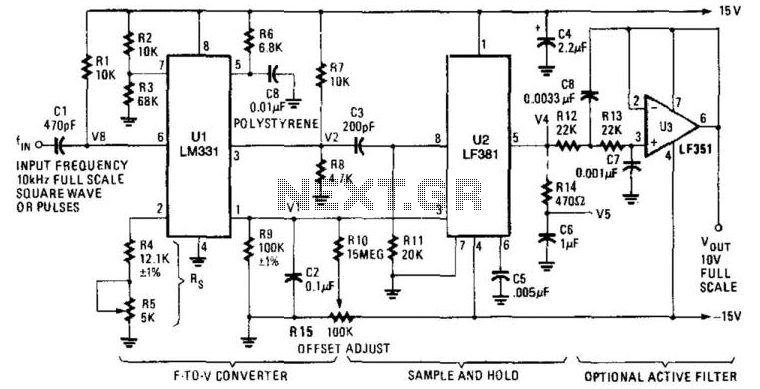
U1 is a frequency-to-voltage converter that feeds a sample-and-hold circuit utilizing an LF381 operational amplifier. An LF351 provides a 10-V maximum scale output. The circuit generates a 1-V output per kHz frequency. The described circuit employs a frequency-to-voltage conversion technique,...
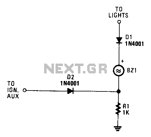
When both the ignition and the car lights are activated, piezo transducer BZ1 does not draw any current and remains silent. If only the ignition is on, diode D1 is reverse-biased, which prevents current from flowing through BZ1. However,...
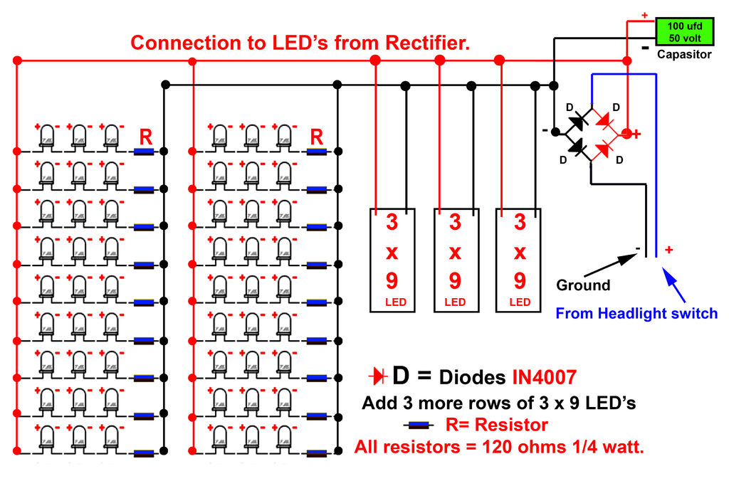
Gently bend the leads of the LEDs and, using the provided schematic circuit diagram, begin to solder. Once soldering is complete, it should... To successfully assemble the LED circuit, it is essential to follow a systematic approach. Start by preparing...