
Lithium battery indicator
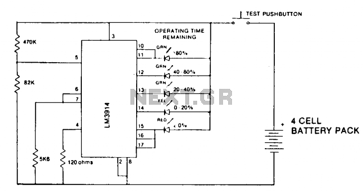
The circuit for the state-of-charge indicator typically employs a voltage comparator to monitor the voltage levels of a battery pack, specifically a 4-cell arrangement. The voltage range of 9.6 to 5.2 volts corresponds to the nominal fully charged state and the cut-off voltage for the cells. The voltage comparator is configured to compare the voltage from the battery cells against a reference voltage, which is set to indicate specific charge levels.
In this configuration, the battery voltage is fed into the non-inverting input of the comparator, while the reference voltage is connected to the inverting input. As the battery discharges, its voltage decreases, and when it falls below the reference voltage, the output of the comparator changes state, triggering an LED or another visual indicator. This provides a clear visual representation of the state of charge.
The circuit can be designed with hysteresis to prevent rapid toggling of the output due to noise or small fluctuations in the battery voltage. Additionally, resistors and capacitors may be included to fine-tune the response time and stability of the circuit. The choice of components, such as the comparator IC and the visual indicator, should be made based on the intended application and the desired sensitivity and accuracy of the state-of-charge indication.
Overall, this voltage comparator circuit serves as an effective solution for monitoring the state of charge in battery management systems, particularly for applications involving multiple cells in series.State-of-Charge indication of-a sloping-voltage discharge can be used as a state-of-charge indicator. A typical voltage comparator circuit that gives a visual indication of state-of-charge is shown. Components identified are for a 4-cell input voltage of 9.6 to 5.2 volts. 🔗 External reference
Related Circuits
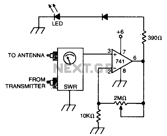
An operational amplifier (op amp) receives a direct current (DC) input from a standing wave ratio (SWR) meter, which can be adjusted to preset the SWR reading at which the light-emitting diode (LED) activates. The circuit involves an operational amplifier...
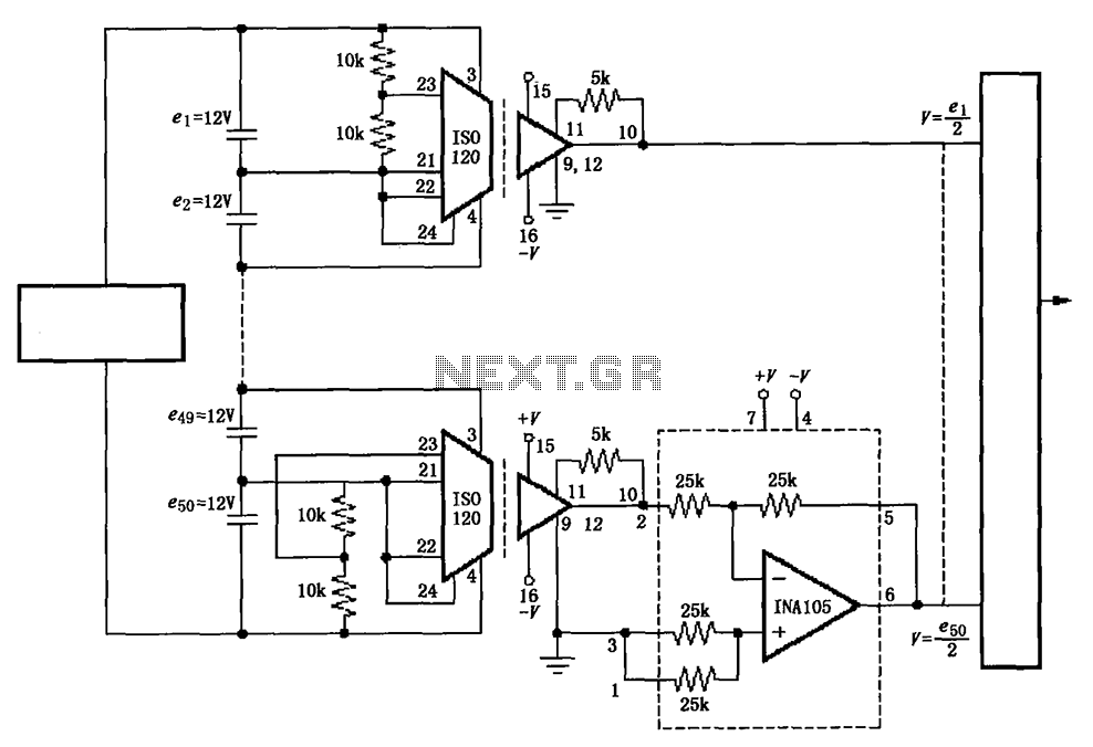
The circuit utilizes the ISO120 and INA105 instrumentation amplifiers to create a battery monitoring system for a 600V battery setup composed of 50 series-connected 12V batteries. This circuit is designed to detect charging and discharging conditions to prevent overcharging...
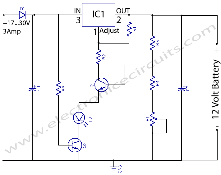
12 Volts Lead Acid Battery Charger Circuit. Apart from serving as a standard battery charger, this circuit is ideal for providing a constant charge to a 12-Volt lead-acid battery. This 12-Volt lead-acid battery charger circuit is designed to efficiently charge...
Traditional guitar amplifier tubes, such as the 12AX7, utilize indirectly-heated cathodes. In this configuration, the heating filament is electrically isolated from the cathode, which emits signal-producing electrons. This design simplifies the circuit significantly, allowing the cathode voltage to be...
A window comparator formed by two operational amplifiers packaged into IC1 is the heart of the circuit below. With this technique, we can detect precisely and symmetrically. The window comparator circuit utilizes two operational amplifiers (op-amps) configured to create a...
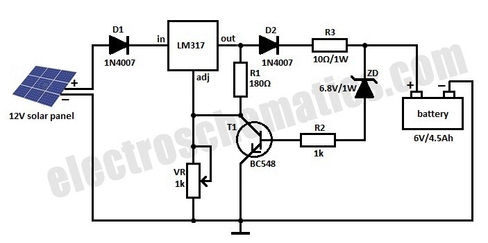
This is a solar charger circuit designed to charge Lead Acid or Ni-Cd batteries using solar energy. The circuit captures solar energy to recharge a 6-volt, 4.5 Ah rechargeable battery for various applications. It includes voltage and current regulation...
Warning: include(partials/cookie-banner.php): Failed to open stream: Permission denied in /var/www/html/nextgr/view-circuit.php on line 713
Warning: include(): Failed opening 'partials/cookie-banner.php' for inclusion (include_path='.:/usr/share/php') in /var/www/html/nextgr/view-circuit.php on line 713