
DIY Full LED 600+ Lumens LED Headlight
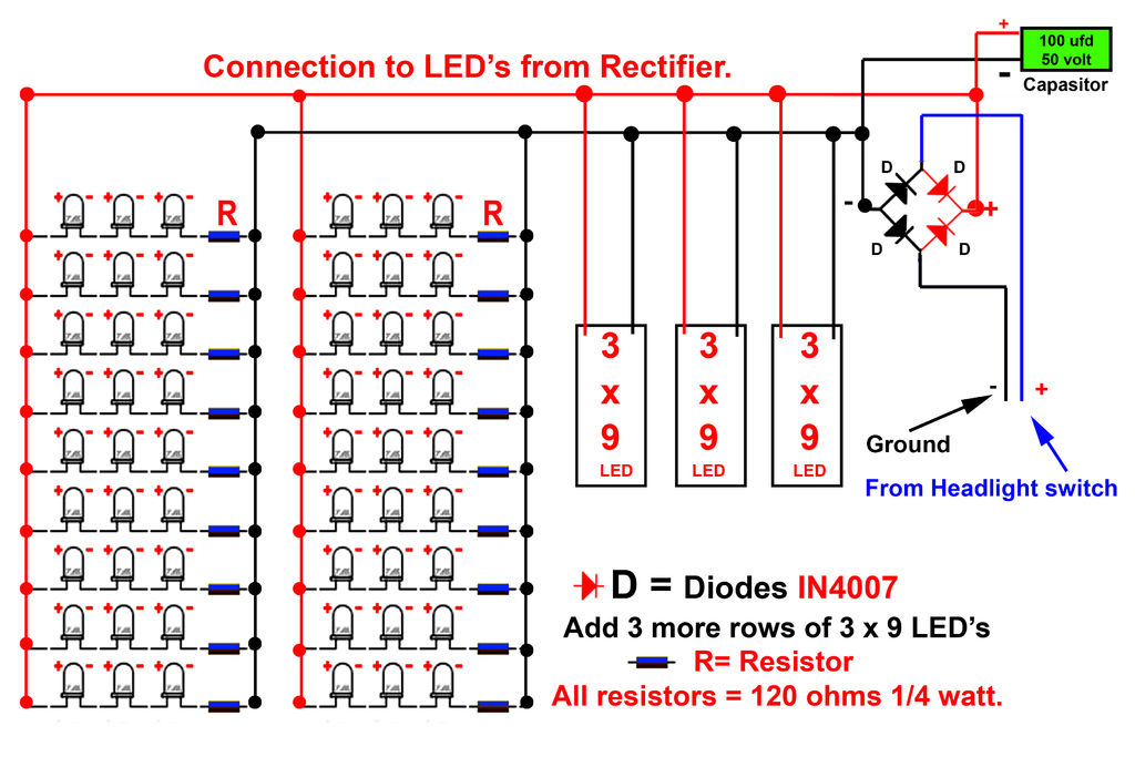
To successfully assemble the LED circuit, it is essential to follow a systematic approach. Start by preparing the workspace and ensuring all components are readily available. The schematic diagram serves as a crucial reference throughout the assembly process, illustrating the correct connections and orientations for each component.
Begin with the LEDs, which should be oriented correctly according to their anode and cathode leads. The anode is typically the longer lead and should connect to the positive voltage supply, while the cathode connects to the ground or negative side of the circuit. Gently bending the leads of the LEDs will facilitate easier insertion into the PCB or breadboard, ensuring a secure fit.
Before soldering, double-check the schematic to confirm that the LEDs are placed in the correct positions and that any necessary resistors are included in the circuit to limit current and prevent damage to the LEDs. The resistors should be chosen based on the specifications of the LEDs being used, considering their forward voltage and current ratings.
Once the components are positioned correctly, proceed to solder the connections. This involves heating the solder joint with a soldering iron until the solder flows and forms a solid connection. Care should be taken to avoid overheating the components, which could lead to damage. After soldering, inspect each joint for quality, ensuring that there are no cold solder joints or bridges between adjacent connections.
After completing the soldering process, it is advisable to test the circuit before finalizing the assembly. This can be done by applying power to the circuit and observing the LEDs for proper illumination. If any LEDs do not light up, it may indicate an issue with the connections or component orientation that requires troubleshooting.
In conclusion, meticulous attention to detail during the assembly of the LED circuit is crucial for ensuring functionality and reliability. Following the schematic diagram closely and adhering to proper soldering techniques will result in a successful circuit build.Now gently bend the leads of the LEDs and using the schematic circuit diagram given below begin to solder Once you finish soldering, it shoul.. 🔗 External reference
Related Circuits

This is a 220V LED flasher circuit designed as a reliable alternative to thermally-activated switches for flashing Christmas tree lamps. The circuit is cost-effective and easy to assemble. Schematic diagram: Component Parts: R1 10Ω. The 220V LED flasher circuit operates...

The main technical characteristics of the MAX7316 include a 400 kbps, 2-wire serial interface with a voltage tolerance of 5.5V. The operating voltage ranges from 2V to 3.6V. It features 8-bit PWM control for white LED brightness, with global...

This project has been in development for over a year, initially postponed due to concerns about design complexity and the availability of high-quality phono preamps. The objective was to create a preamp that would deliver performance comparable to commercial...

An array of white LEDs can serve as a compact lamp for living spaces. These LED lamps are commercially available and resemble standard halogen lamps, fitting into typical 230-V light fixtures. Upon inspection, it is evident that a capacitor...

The LM3434 adaptive constant on-time DC/DC buck (step-down) constant current controller can be used to design a simple high-power LED driver application. The LM3434 provides a constant current for illuminating high-power LEDs. The output configuration allows the anodes of...

This white LED driver circuit project utilizes the NCP5680 high-efficiency white LED driver integrated circuit (IC). The NCP5680 supports dual power flash LED and torch operations. Its built-in DC/DC converter employs a highly efficient charge pump structure with operating...