
6 Zone Alarm System
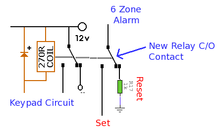
The alarm system is designed to provide comprehensive security coverage across multiple zones, ensuring immediate detection of unauthorized access while allowing for a timed exit period. The integration of CMOS technology enhances reliability and power efficiency, making it suitable for various applications in residential and small commercial settings. The use of a seven-segment display facilitates user interaction by clearly indicating the status of the alarm and which zone has been triggered, thus enhancing the overall functionality of the system. The design consideration for RF immunity through the use of input capacitors further ensures the robustness of the alarm system, minimizing false alarms that could arise from electrical interference. The implementation of a metal key switch for setting and resetting the alarm adds a layer of physical security, preventing unauthorized access to the alarm controls. This alarm system exemplifies a well-engineered solution for effective perimeter security in environments where rapid response to unauthorized entry is critical.This alarm system has 6 independent zones, 1 timed entry/exit zone, a 7 segment LED display and a test or walkthrough facility. Suitable for a small office or home environment, it can also be adapted to use a combination lock or keypad to set and reset the alarm.
Please Note: All orange +V terminals connect to the point marked +5V at the side of t he set switch, S1. IC`s U1, U2, U3, U4, U5 and U7 are drawn without power connections for clarity. The power connections need to go +5V and ground. See Practical Section for IC pinouts and relay contacts. All zones Z1 to Z6 use normally closed alarm contacts. Zone 1 is a timed zone which must be used as the entry and exit point of the building. Zones 2 to 6 are immediate zones, which will trigger the alarm with no delay. Some RF immunity is provided for long wiring runs by the input capacitors, C1 - C6. The key switch, S1 acts as the Set and Reset/Unset switch. For best security this should be the metal type switch with a key. All IC`s except IC6 are CMOS types with buffered outputs, these are denoted by the suffix "B". Unbuffered CMOS IC`s have a suffix starting "U" and will not work in this circuit. IC6 is a 5 Volt regulator providing power to the main CMOS IC`s, the alarm power supply can be any suitable 12 to 15V power supply. In operation the DPDT switch S2 is set to the "run" position. When keyswitch S1 is turned reset, this is the unset (off) state of the alarm. In this condition capacitor C8 will discharge via D9, R1 and Z1 and capacitor C7 will have discharged via D8, R17 and S1.
Relay RLY1 will not be energized and all CMOS IC`s and the display will have no power. When S1 is turned to set all CMOS IC`s receive 5 Volt power. C11 will briefly charge and apply a low input signal to one half of U7A a CMOS4001B, a dual input OR gate. The output of U5A will also be low (make sure all windows and doors zones 2 to 5 are shut) and the output of U7A is high.
The output of U7A is then inverted by U7B and fed back via R18 to U7A`s input keeping the circuit latched. The output of U7B is low and so Q1 and the relay RLY1 is off and no alarm will sound. Also when S1 is set, C8 slowly charges via R13. C8 and R13 form the exit timer and allow time to vacate the building. The delay is approximately 1. 1 x the value of C8 (in uF) or about 52 seconds with values shown. During the exit delay zone switch Z1 can be opened and closed without triggering the alarm. After the exit time ends, C8 will be charged and one half of the 2 input AND gate, U4A will now be high.
Any opening of zones 2 through 6 will cause the alarm to trigger and relay RLY1 will energize. If an intruder attempts a break-in via zone 4 for example, the output of U1D will change state from low to high. When this happens, the high signal is forwarded by U2C a triple input OR gate CMOS4075 and is sent to input C on the CMOS4511 BCD to Decimal display driver.
The binary code for four is 100 and input C is high, A abd B are low, and the LED display will illuminate digit 4. The high output from U2C is also forwarded to U5A, again a triple input OR gate. The output of U5A is now sent via S2 to the input of U7A. U7A and U7B form a bistable latch, the change in state causing the output of U7A to change to low, the output of U7B to become high and fed back via R18 to the input of U7A again.
The circuit is now latched in the high state. The high output of U7B does two things. First it switches on Q1 and relay RLY1 sounding the alarm. Secondly the high output at U7B is applied to the blanking input of the CMOS4511B via S2 and also to the enable latching pin. The display will now continually show the number of the triggered zone, even if the zone switch is opened or closed again.
It is a similar process for any of the other immediate zones. As this alarm uses 6 zones, the CMOS 4511 BCD to decimal decoder must count to 6 which is 110 in binary. Therefore only inputs A, B and C are 🔗 External reference
Related Circuits
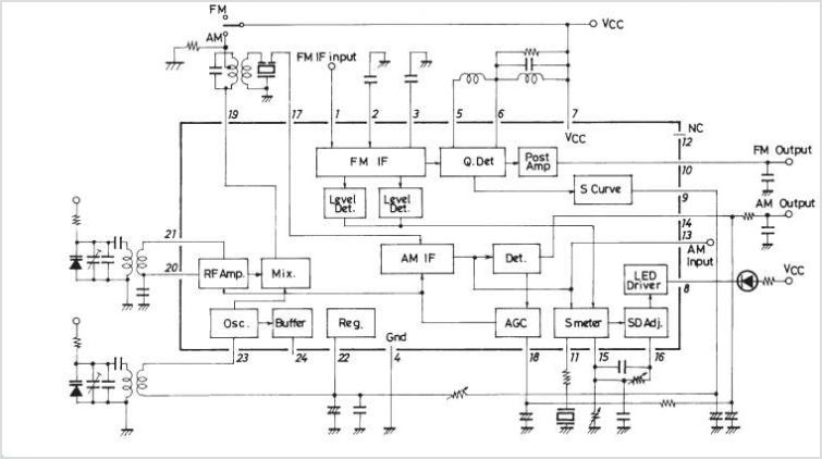
The LA1600 is an AM tuner integrated circuit (IC) housed in a 9-pin single in-line package (SIP). It provides the functionality of an AM tuner and is capable of operating within the shortwave (SW) band range. This IC is...
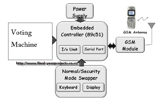
This project involves a GSM-based voting machine system that utilizes AT commands to send SMS through a microcontroller. It operates in two modes: Normal mode, where an authorized individual from a local area can cast their vote, and Security...
The following circuit illustrates a 12-volt modular burglar alarm sensor circuit diagram. Features include a timed bell cut-off, as well as automatic exit and entry functions. The 12-volt modular burglar alarm sensor circuit is designed to provide effective security monitoring...
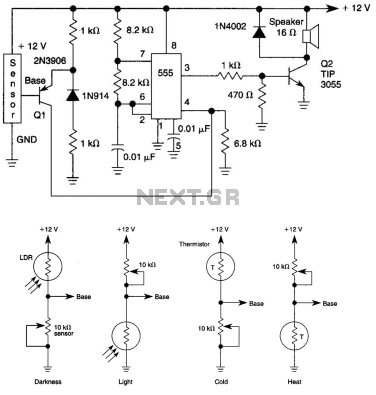
The tone generated by a 555 oscillator can be activated by heat or light, which causes Q1 to conduct transistor Q2 (TIP 3055). Q2 (TIP 3055) functions as an audio amplifier and speaker driver. The circuit utilizes a 555 timer...
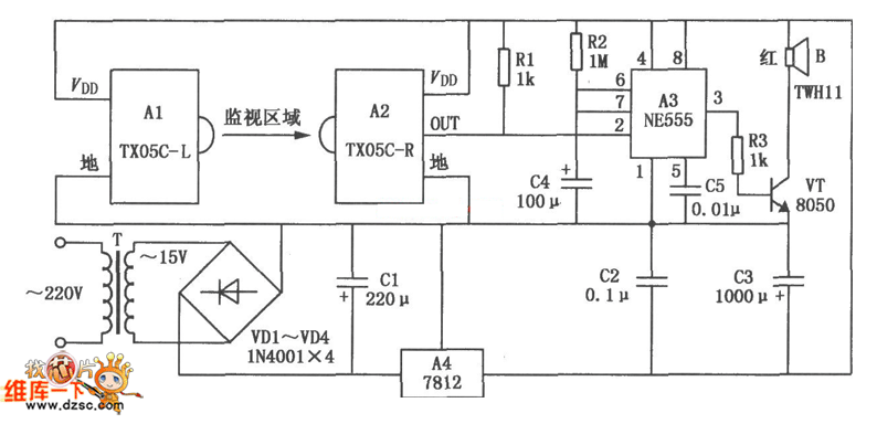
The TX05C-R infrared surveillance alarm circuit is designed for monitoring walls, windows, doors, and various restricted areas. When an intrusion occurs, the alarm activates to enhance security. The circuit comprises a transmitter module, a receiver module, a time-base circuit,...
The Lorenz system is one of the few standard oscillators commonly used to explore chaos. An accessible description of its mathematical features and chaotic dynamics is presented by Thompson and Stewart. This important system was originally developed as a...