
Heat Or Light Activated Alarm Circuit
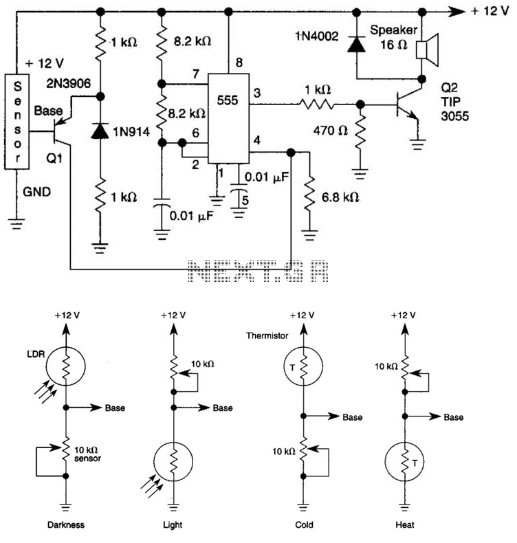
The circuit utilizes a 555 timer configured in astable mode to generate a square wave output that produces a tone. The activation mechanism relies on a heat or light sensor, which, when triggered, allows current to flow through Q1, a transistor that acts as a switch. This switching action enables Q2, also a TIP 3055 transistor, to amplify the audio signal generated by the 555 timer.
In this configuration, the 555 timer's output frequency can be adjusted by varying the resistor and capacitor values connected to it. The output from the 555 timer feeds into the base of Q2, which amplifies the signal significantly. The TIP 3055 is chosen for its ability to handle higher currents and voltages, making it suitable for driving a speaker directly.
The circuit may include additional components such as resistors for biasing the transistors, capacitors for filtering, and possibly a diode for protection against back EMF generated by the speaker. The speaker, connected to the collector of Q2, produces sound when the amplified signal drives it. This arrangement allows for a responsive audio output that reacts to environmental changes detected by the heat or light sensor. The tone generated by a 555 oscillator can be turned on (activated) by heat or light. That causes Ql to conduct transistor W2 (TIP 3055). Q2 (TIP 3055) acts as an audio amplifier and speaker driver. 🔗 External reference
Related Circuits
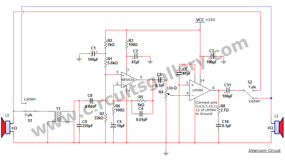
An intercom or intercommunication circuit is a two-way communication system that provides a reliable communication line and is easy to implement. The circuit consists of an amplifier, two switches, and two loudspeakers, allowing for the extension of the system...
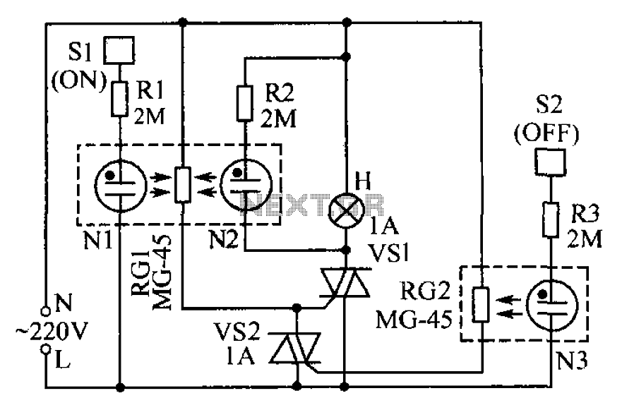
The circuit operates based on the principle that neon tubes N1, N2, and the photosensitive resistor RG1 form an optocoupler. When a finger touches the metal sheet S1, N1 lights up, causing RG1's resistance to decrease. This reduction allows...
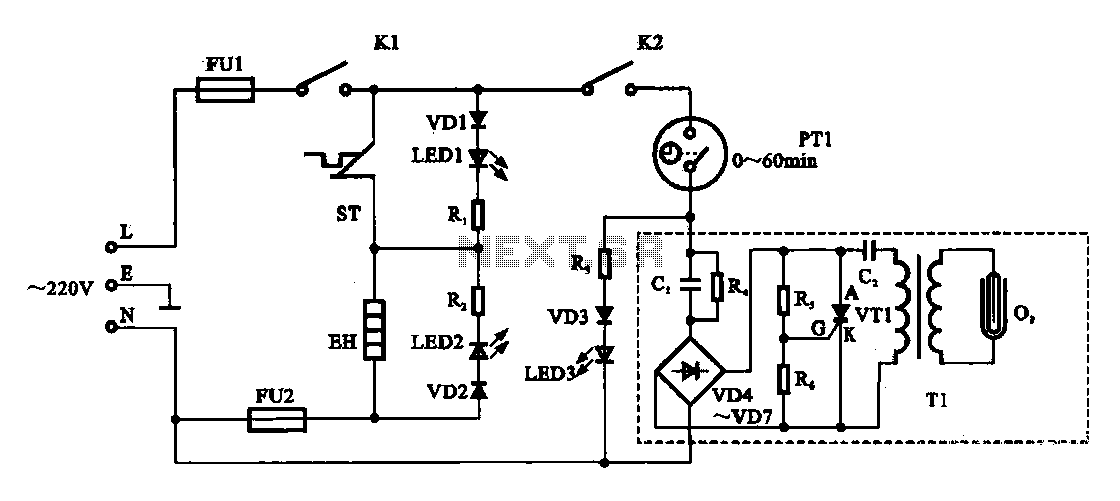
The dispenser (Aucma) temperature detection control circuit is designed to manage the temperature of the dispenser. It consists of two primary components: a heating control circuit and a fresh cabinet control circuit that provides power to an ozone generator....
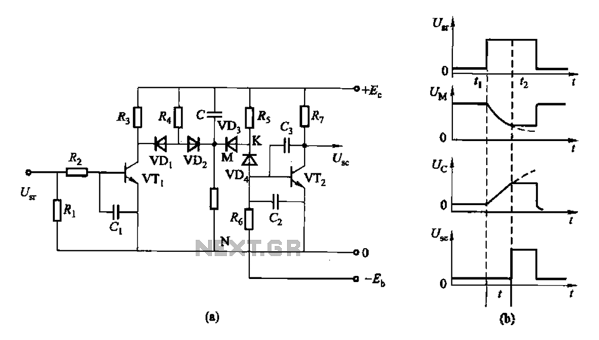
This is a control rechargeable delay circuit. Under normal circumstances, when there is no input signal, the transistor VTi is off. VTz is conducting, resulting in a low output potential (U). When a signal is applied, VTi turns on,...
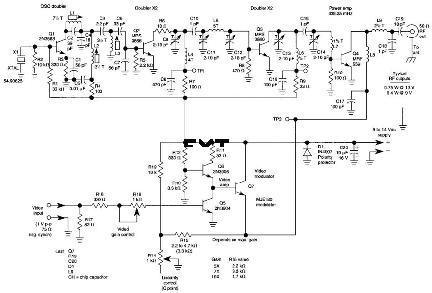
The three schematics illustrate three building blocks for a 10-meter SSB transmitter. These blocks can also be utilized independently as circuit modules for other transmitters. The VFO board incorporates an FET transmission oscillator, with the VFO signal being mixed...
Surround Sound Decoder circuit diagram. The circuit's operation begins when the stereo sound signal carries surround sound information through the master volume section. This drives the Left channel (Lch), which is connected to Model TL072 IC1A and IC1B, with...
Warning: include(partials/cookie-banner.php): Failed to open stream: Permission denied in /var/www/html/nextgr/view-circuit.php on line 713
Warning: include(): Failed opening 'partials/cookie-banner.php' for inclusion (include_path='.:/usr/share/php') in /var/www/html/nextgr/view-circuit.php on line 713