
60 Watt switching Power supply

The described circuit is a practical implementation of an off-line switching power supply utilizing a discontinuous flyback topology. This design is primarily focused on efficiency and performance, leveraging the capabilities of the Unitrode UC3840 integrated circuit for PWM control. The UC3840 is well-regarded for its voltage-feed-forward feature, which enhances output regulation by compensating for variations in input voltage.
The circuit is designed to operate from a 117V AC line, with a tolerance of ±15%, at a frequency of 60 Hz. The output specifications are critical, with two distinct voltage levels: +5V with a tolerance of ±5% at a current range of 2.5A to 5A, and +12V with a tolerance of ±3% at a current range of 1A to 2.9A. The maximum ripple voltage for the +5V output is constrained to 50mV peak-to-peak, while the +12V output is limited to 100mV peak-to-peak. The overall efficiency of the power supply is designed to be a minimum of 70%, and it is capable of withstanding line isolation of up to 3750V.
The flyback topology is selected for its inherent advantages, particularly for power levels below 150W. The design complexity of the power transformer is minimized, and the overall component count is reduced, which translates to lower assembly costs. The flyback converter utilizes a single magnetic element, the transformer, eliminating the need for additional inductors in the output filter stage. This simplicity not only reduces costs but also enhances reliability.
In terms of component selection, attention is given to the transformer design to ensure that it meets the required specifications for efficiency and voltage regulation. The control loop is meticulously designed to maintain stability and dynamic response, ensuring that the power supply performs effectively under varying load conditions. Overall, this design exemplifies a well-structured approach to creating an efficient and reliable switching power supply using a flyback converter topology.This paper gives a practical example of the design of an off-line switching power supply. Factors governing the choice of a discontinuous flyback topology are discussed. The design uses a pulsed-width modulation (PWM) control scheme implemented with a Unitrode UC3840 IC. This chip's voltage-feed-forward feature is used to achieve improved output regulation. The paper discusses closing the control loop to achieve both stability and adequate dynamic regulation, and provides guidelines for transformer design and component selection.
The circuit developed herein operates from a l17V (::!::15%), 60 Hz line and meets the following objectives: I. Output voltages: a. +5V, :!::5%: 2.5A-5A Ripple voltage: 50mV p-p maximum b. +12V, :!::3%: IA-2.9A Ripple voltage: lOOmV p-p maximum 2. Fificiency: 70% minimum 3. Line isolation: 3750V These objectives are met by using a flyback converter topology with a MOSFET power switch operating at 80kHz.
The design features primary side control. I. SELECTION OF FLYBACK TOPOLOGY The flyback, when compared to other switching regulator topologies, has several cost and performance advantages: Cost Advantages: 1. For output power levels less than -150W, the design of the power transformer (coupled inductor) is relatively simple.
2. Assembly costs for the flyback regulator are low due to a low overall component count. In particular, only one magnetic element (i.e., the transformer) is employed as no inductors are used in the output filters. 3. Output rectifier BY requirements are low, since they do not need to block voltages which in other topologies are developed across the fIlter inductor.
🔗 External reference
Related Circuits
Currently, a basic MOSFET amplifier or power amplifier is designed to deliver an output power of ±100 Watts RMS with an 8 Ohm load, or ±160 Watts RMS with a 4 Ohm load. The simplicity of this circuit results...
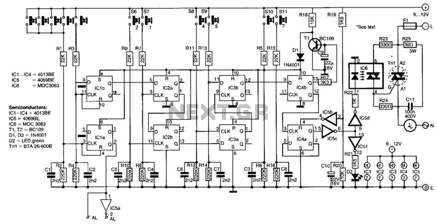
This switch utilizes four CD4013BE dual flip-flops, an inverter, and an optoisolator to control a triac, allowing it to switch a 25-A AC load current. A standard 4x3 telephone keypad is employed for entering a 6-digit code. In the...
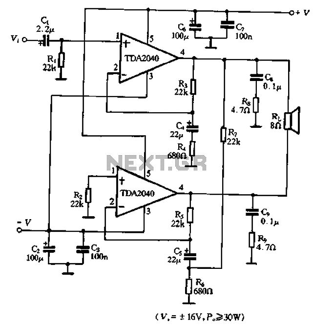
The TDA2040 is a power audio amplifier with a wider operating voltage range compared to the TDA2030, ranging from 4V to 20V. It can deliver an output power of 18W at a load of 4 ohms when supplied with...
High power amps are not too common as projects, since they are by their nature normally difficult to build, and are expensive. A small error during assembly means that you start again - this can get very costly. I...
The LM3886 is an improved version of the LM3875. Key features of the LM3886 include a maximum output power of 68W RMS and 108W peak, with a total harmonic distortion (THD) of 0.03% at 60W. The LM3886 is a high-performance...
The circuit described here was designed as an addition to a remotely controlled garage door opener. The problem was that a brief burst of interference, arising from a thunderstorm or a mains spike, was enough to trigger the mechanism,...