
Mosfet Power Amplifier 100 Watt Schematic Diagram
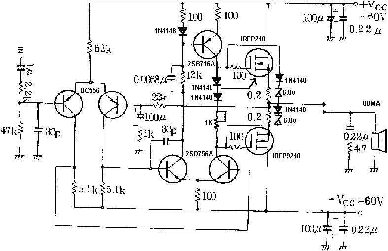
The described MOSFET amplifier circuit operates as a straightforward yet effective power amplifier, utilizing MOSFET technology to achieve high output power levels suitable for various audio applications. The design's choice of ±100 Watts RMS at 8 Ohms and ±160 Watts RMS at 4 Ohms indicates a robust capability to drive speakers with different impedance levels, catering to diverse sound system requirements.
The distortion specification of ±0.1% is commendable for a circuit of this simplicity, suggesting that the amplifier can deliver clean audio signals with minimal coloration. The bandwidth of 4 Hz to 96 kHz is suitable for high-fidelity audio reproduction, allowing the amplifier to handle a wide range of frequencies from deep bass to high treble without significant attenuation or distortion.
Key components, such as capacitors C1 and C2, play a crucial role in shaping the frequency response and stability of the amplifier. Resistors R1 and R2 help set the gain and stabilize the circuit, ensuring that the amplifier performs consistently across its operating range. The differential stage formed by transistors T1 and T2 is essential for amplifying the input signal while maintaining linearity and low distortion.
The current source, implemented with resistor R3, provides a stable biasing condition for the transistors, which is vital for maintaining performance across temperature variations and component aging. The upgrade to a more efficient current source enhances the overall stability of the amplifier, reducing the risk of thermal runaway and improving reliability.
Coil P1 serves as a critical tuning element, allowing for precise adjustments to the output voltage. This tuning capability is particularly valuable during the initial power-up phase, where careful adjustments can prevent undesirable DC offsets that may damage connected speakers or compromise audio quality. The emphasis on using high-quality components throughout the design underscores the importance of reliability and performance in audio applications, ensuring that the amplifier meets the expectations of discerning users.At this time a unsophisticated MOSFET amplifier or else power Amp which Output power is plus/minus 100 Watt/RMS with8 Ohms otherwise ohter plus/minus 160 Watts /RMS with 4 ohms. Regarding this circuit simplicity, The distortion is plus/minus 0. 1 %. In support of mob-width -3 db(decibel) is increase for 4 Hz to 96 Khz, it is narrow by C1, R1, C2 and
R2. Taking part in the two transistors are T1 and T2 makes a initial differential stage part, So, current source(I) of +/- solitary mA is put with resistor R3. In favor of the upgraded project, The current source(I) is new efficient in stability. Coil P1 allows a fine tuning of dictate current voltage on amplifier`s output. Place the Coil P1 with it`s partially usefulness in favor of first power up, so therefore break it unhurriedly for a lowest DC output voltage.
custom a essential quality compoment. 🔗 External reference
Related Circuits
The D-200W module features a unique design that includes overload, overvoltage, overheating, short circuit, and reverse polarity protection, as well as shock protection for various speakers. The module employs a synchronous dynamic bias circuit to minimize static power consumption,...
This low-cost project enables audio reproduction from a television without disturbing others. It eliminates the need for wired connections between the TV and loudspeakers. Instead, it utilizes invisible infrared light to transmit audio signals from the TV to the...
The flash beam can be utilized to power remote control devices for AC power applications. A key feature of this device is its memory function, which allows it to supply power continuously. Upon the second activation, the power will...
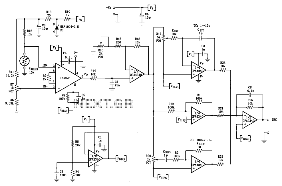
The INA326/327 forms a single power PID (proportional-integral-derivative) controller as illustrated in the temperature control loop. This circuit is primarily designed for temperature measurement and control. A thermistor, designated as RTHERM, detects temperature changes and converts them into an...
The LM231 and LM331 family of voltage-to-frequency converters are well-suited for use in simple, low-cost circuits designed for analog-to-digital conversion, precision frequency-to-voltage conversion, long-term integration, linear frequency modulation or demodulation, and various other applications. When utilized as a voltage-to-frequency...
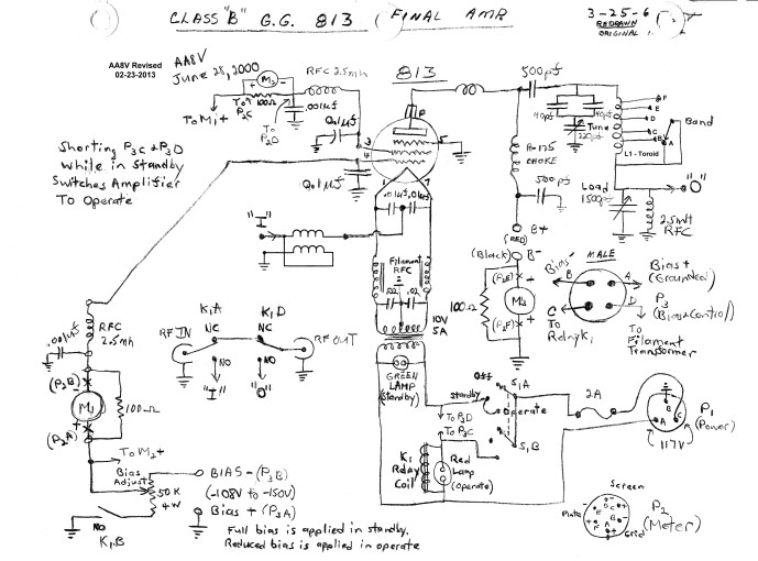
The input impedance of a grounded grid amplifier is typically several hundred ohms. While most vacuum tube transmitters can drive such an impedance without issue, solid-state transmitters, which are designed for loads close to 50 ohms, generally struggle with...
Warning: include(partials/cookie-banner.php): Failed to open stream: Permission denied in /var/www/html/nextgr/view-circuit.php on line 713
Warning: include(): Failed opening 'partials/cookie-banner.php' for inclusion (include_path='.:/usr/share/php') in /var/www/html/nextgr/view-circuit.php on line 713