
300W Subwoofer Power Amplifier

Additional Content: The high power amplifier being referred to here is a complex electronic assembly that requires a substantial degree of technical knowledge and practical experience to construct. These amplifiers are not generally used as beginner projects due to their inherent complexity and cost. They require precise assembly and even a minor mistake can necessitate a complete reassembly, leading to significant additional costs.
The recommendation to use Printed Circuit Board (PCB) for this amplifier is due to its ability to streamline the assembly process and minimize potential errors. PCBs provide a physical platform for mounting and interconnecting components, which can significantly reduce the complexity of wiring and soldering, thereby mitigating the risk of assembly errors. However, it should be noted that the assembly of this amplifier on a PCB still requires a certain level of expertise.
This amplifier is not suitable for beginners who are only familiar with Veroboard, a type of prototyping board characterized by a grid of holes and pre-made tracks for easy component insertion and soldering. The complexity of a high power amplifier exceeds the capabilities of a Veroboard and demands a more advanced platform like a PCB.
The assembly of this high power amplifier can be accomplished by a reasonably experienced hobbyist in approximately three hours. This timeline, however, is subjective and may vary depending on the individual's skill level and familiarity with the components and assembly process. It is advised that individuals undertaking this project have a thorough understanding of electronic circuit design and assembly, as well as the specific requirements of high power amplifiers.High power amps are not too common as projects, since they are by their nature normally difficult to build, and are expensive. A small error during assembly means that you start again - this can get very costly. I recommend that you use the PCB for this amplifier, as it will save you much grief. This is not an amp for beginners working with Veroboard! The amplifier can be assembled by a reasonably experienced hobbyist in about three hours. 🔗 External reference
Related Circuits
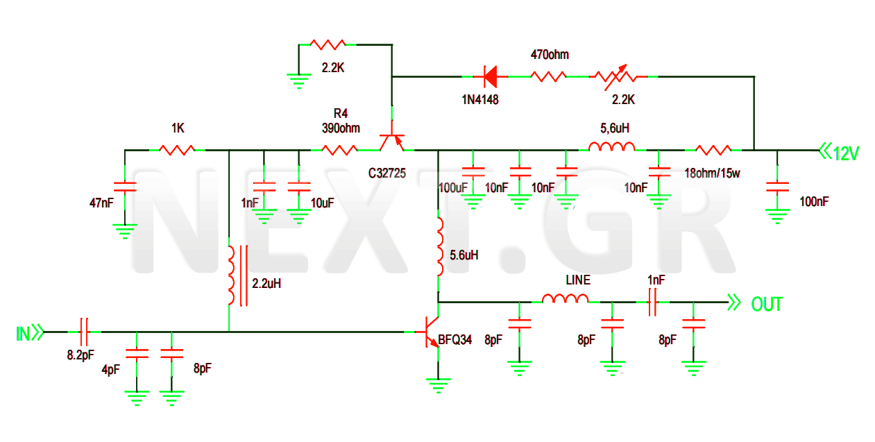
This project involves the construction of a VHF-UHF linear amplifier capable of operating at frequencies ranging from 47 MHz to 740 MHz. It serves as the final output stage for any transmitter functioning within these frequencies. The amplifier utilizes...
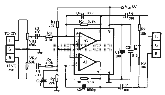
The TDA1308 is a Class AB headphone driver integrated circuit (IC) recently launched by Philips. Its primary features include a compact size and low power consumption, making it particularly suitable for portable CD players and other digital audio devices....
The LME49830 EF125WT1 amplifier PCB module features National Semiconductor's LME ultra-high fidelity power amplifier input stage integrated circuits (ICs) designed for driving applications. The LME49830 EF125WT1 amplifier PCB module is engineered to deliver exceptional audio performance, capitalizing on the advanced...
This device, available in a Stainless DIL 8 package, is capable of measuring four independent analog voltages ranging from 0 to 5 volts. It transmits the measurement results as four characters via a standard asynchronous serial link. The described device...

Voltage is transformed by the transformer turns ratio N2/N1. For instance, if a 20VAC secondary voltage is required with a 120VAC input, a 6:1 ratio would be needed. When full load current is drawn from the secondary winding, the...
This design is based on an 18 Watt audio amplifier and was developed primarily to meet the needs of users who are unable to find the TLE2141C chip. It utilizes the widely available NE5532 dual integrated circuit; however, its...