
60W audio amplifier (2N3055)
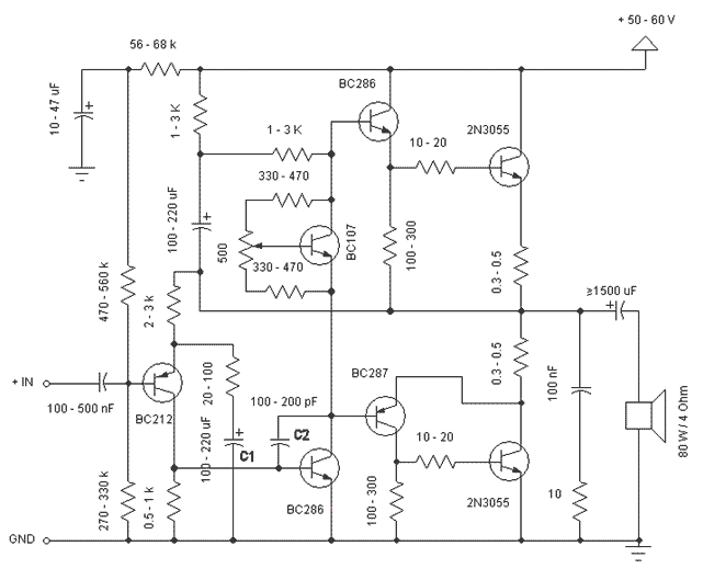
The described circuit is a 60W class B power amplifier designed for audio applications. The power supply voltage range of 30V to 60V allows for flexibility in component selection and system integration. The optimal operating point is at 50V, which is crucial for achieving the desired output power while maintaining efficiency.
The input stage of the amplifier accepts a maximum input voltage of 0.8V to 1V, indicating that it is tailored for line-level audio signals. The design accommodates a variety of NPN transistors for the output stage, excluding Darlington pairs due to their higher saturation voltage which can affect performance in this application.
Capacitors C1 and C2 play a significant role in audio frequency response. C1 is responsible for coupling low-frequency signals, enhancing bass response as its capacitance value increases. Conversely, C2 manages high-frequency signals, where an increase in capacitance results in attenuation of treble frequencies. This frequency management allows users to tailor the amplifier's sound characteristics to their preferences.
The inclusion of a 500 Ohm trimmer resistor for biasing the output transistors is a critical feature. In class B amplifiers, a small bias current must flow through the output transistors to minimize crossover distortion. Adjusting this trimmer allows for optimization of sound quality at the expense of thermal performance, as higher bias currents lead to increased heat dissipation in the transistors. Conversely, reducing the bias current decreases heat generation but can negatively impact audio fidelity.
Overall, this power amplifier design is characterized by its adaptability, allowing for the use of readily available components while providing essential features for audio signal processing and quality enhancement. The design principles employed ensure that users can achieve satisfactory performance across a range of operating conditions.This is a simple and low cost 60W power amplifier. The optimal supply voltage is around 50V, but this amp can work from 30 to 60V. The maximum input voltage is around 0.8 - 1V. As you can see, in this design the components have a big tolerance, so you can build it with almost any components that you can find at home. The output power transistors can be any NPN types, but do not use Darlington types. Capacitor C1 regulates the low frequencies (bass), as the capacitance grows, the low frequencies are getting louder.
Capacitor C2 regulates the higher frequencies (treble), as the capacitance grows, the higher frequencies are getting quieter. This is a class B amplifier, this means, that a current must flow through the end transistors, even if there is no signal on the input. This current can be regulated with the 500 Ohm trimmer resistor. As this current increases, the sound of the amplifier is better, but output transistors are dispatching more heat.
If the current is decreased, the transistors are dispatching less heat, but the sound quality is decreased. 🔗 External reference
Related Circuits

This series-feedback configuration of components provides a high input impedance and stable, wide-band gain video amplifier suitable for general-purpose applications. Below is the schematic representation of the circuit. The described video amplifier circuit employs a series-feedback topology, which is instrumental...
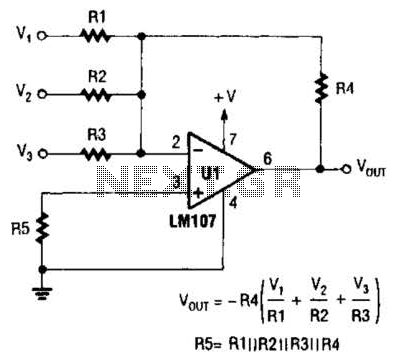
The output of Ul is the sum of Vv, multiplied by the ratio of Rx to Rv, RJRV, and respectively. Resistors R1, R2, and R3 are selected as required for individual gains. Additionally, R4 influences the gain of all...
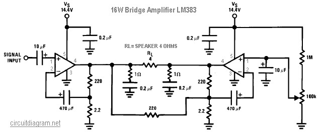
The following diagram illustrates a 16W bridge audio amplifier circuit. The design incorporates two LM383 power ICs in a head connection, making this amplifier a head amplifier. The LM383 is an older model that has been discontinued, which may...

This circuit is designed as a pocket-sized, high-performance audio oscillator. It can operate using a battery-powered version, which is feasible at a very low cost by utilizing a single quad op-amp to provide the entire active circuitry. The design...
The supply voltage should be about +/- 35 Volts at full load, which will let this little guy provide a maximum of 56 Watts (rated minimum output at 25 degrees C). To enable maximum power, it is important to...
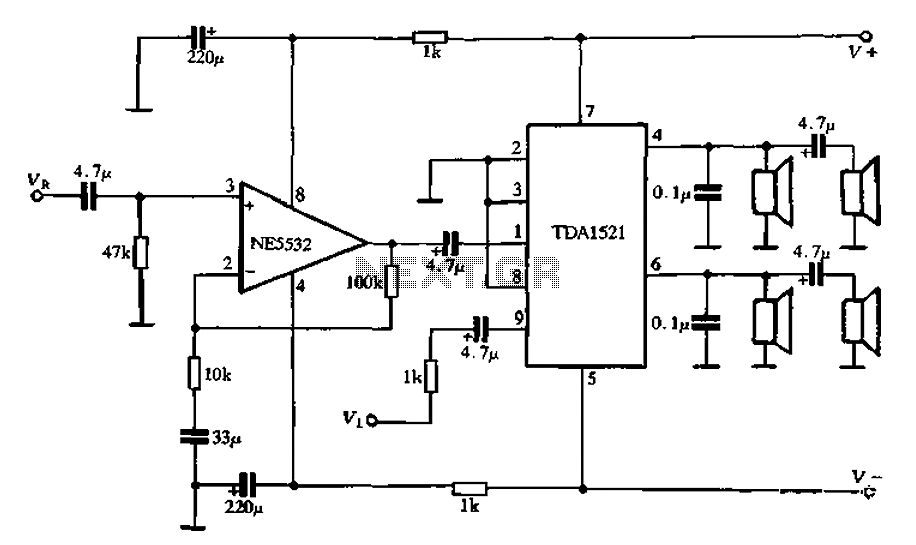
Active speaker with amplifier circuit TDA1521 and NE5532, featuring dual-channel input and dual-channel output. The active speaker circuit utilizes the TDA1521 integrated circuit, which serves as the power amplifier. This IC is designed for high-efficiency amplification, providing a robust output suitable...