
50 Watt Power Amplifier
The described circuit operates with a dual power supply of approximately +/- 35 Volts, allowing for a maximum output power of 56 Watts under full load conditions. This configuration is particularly suited for audio amplification or similar applications where high power and low distortion are critical. The operational amplifier or transistor stage within the circuit must be designed to handle the thermal load effectively. The thermal management aspect is crucial; thus, the heatsink must be mounted directly to the component without an insulating mica washer to minimize thermal resistance. However, it is essential to ensure that the heatsink is properly insulated from the chassis, as it will be at a negative supply voltage, preventing any accidental short circuits or damage to the circuit.
The voltage gain of the amplifier is set at 27dB, which can be adjusted by changing the feedback resistor (R3) currently specified as 22k ohms connected between pins 3 and 9 of the amplification stage. This feedback configuration allows for flexibility in gain adjustment, enabling the designer to tailor the circuit's performance to specific requirements. The inductor used in the circuit is constructed with 10 turns of 0.4mm enamelled copper wire, wound around a core with a resistance of 10 ohms. The choice of wire gauge and the number of turns are critical for achieving the desired inductance and ensuring efficient operation in the intended frequency range.
In summary, attention to thermal management, adjustable gain through feedback resistor selection, and careful inductor design are critical components of this circuit's performance and reliability. Proper implementation of these elements will ensure optimal functionality and longevity of the electronic device.The supply voltage should be about +/- 35 Volts at full load, which will let this little guy provide a maximum of 56 Watts (rated minimum output at 25 degrees C). To enable maximum power, it is important to get the lowest possible case to heatsink thermal resistance.
This will be achieved by mounting with no insulating mica washer, but be warned that the heatsink will be at the -ve supply voltage and will have to be insulated from the chassis. Voltage gain is 27dB as shown, but this can be changed by using a different value resistor for the feedback path (R3, currently 22k, between pins 3 and 9). The inductor consists of 10 turns of 0.4mm enamelled copper wire, wound around the body of the 10 O 🔗 External reference
Related Circuits
A 12-volt relay is connected between two stages such that when it receives 12 volts from the supply, it activates and disconnects the 3-volt DC supply from the melody circuit. Conversely, when mains power is absent, the relay switches...
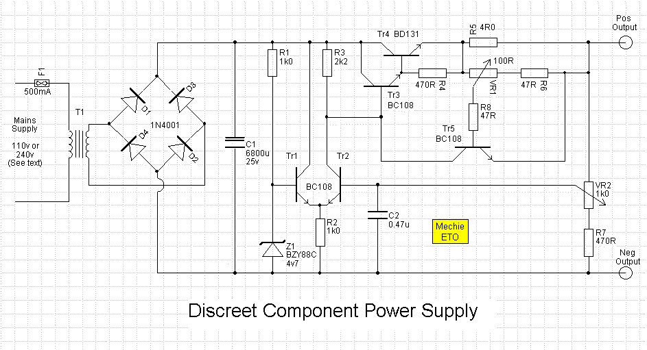
An error amplifier is constructed using transistors Tr1 and Tr2, configured as a differential amplifier, commonly referred to as a long-tailed pair, with the collector leads being a notable feature. One input of this differential amplifier is sourced from...
The GainClone concept appears to have gained considerable traction. There are several compelling reasons for this, and I found myself in a situation where SWMBO (She Who Must Be Obeyed) was becoming increasingly agitated as I added amplifiers and speakers...
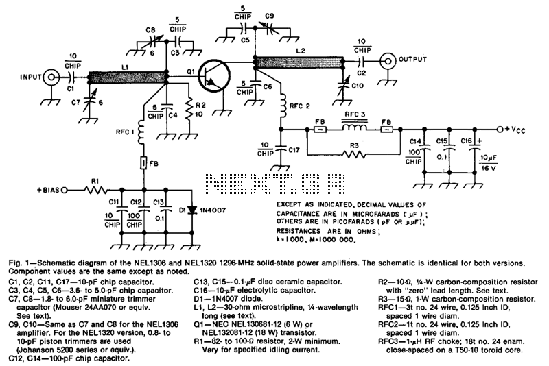
The design incorporates 30-ohm, 1/4 microstrip lines on the input and output. Capacitors C3, C4, C7, and C8, along with inductor L1, form a pi network that matches the low input impedance of the device to 50 ohms. Capacitors...
This circuit is a simple form of the commercial UPS, the circuit provides a constant regulated 5 Volt output and an unregulated 12 Volt supply. In the event of electrical supply line failure the battery takes over, with no...
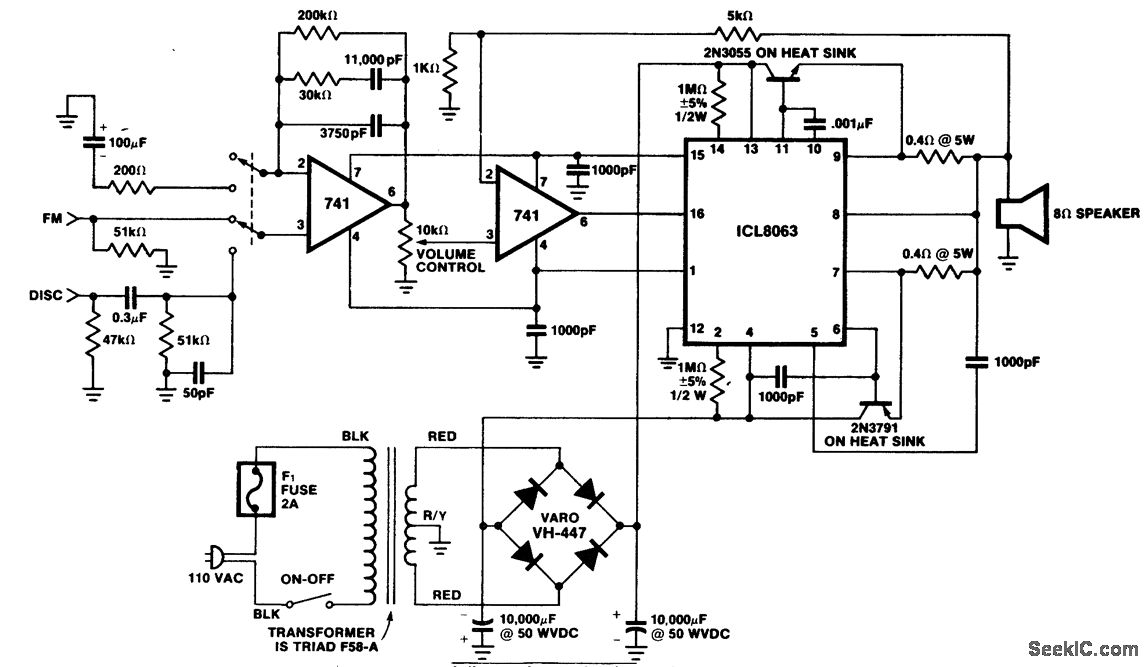
A 50-watt PMS hi-fi amplifier designed for an 8-ohm load. This circuit provides approximately 56 volts peak-to-peak across the 8-ohm load. The distortion level is around 1% at 20 kHz. A ganged switch at the input allows for the...