
60W inverter using transistors
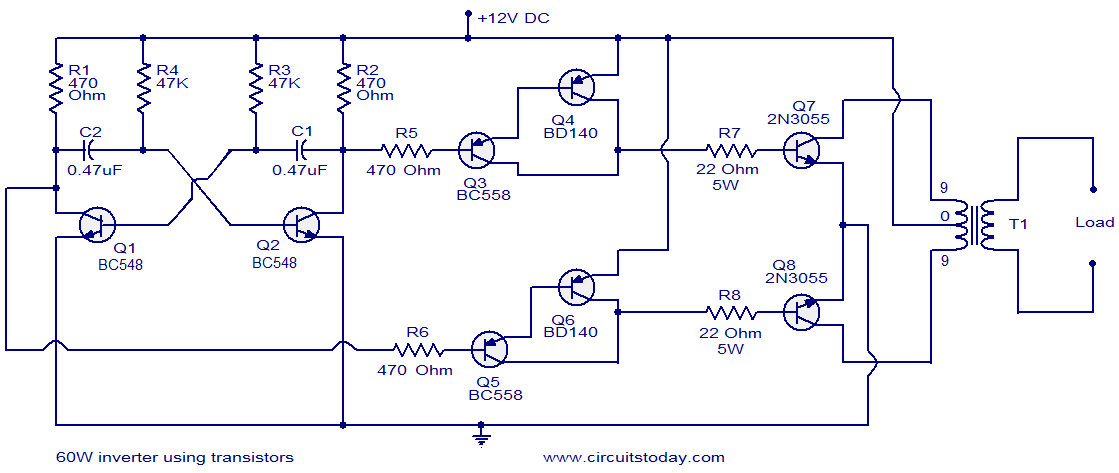
The described inverter circuit is designed to convert DC voltage into an AC voltage suitable for powering various loads. The core functionality is based on an astable multivibrator configuration, which generates a square wave output at a frequency of 50Hz. Transistors Q1 and Q2 operate in this configuration, where they alternately turn on and off, creating a continuous oscillation.
The output from Q2 is fed into the base of the Darlington pair consisting of Q3 and Q4. A Darlington pair is advantageous in this application as it provides high current gain, allowing for efficient switching of larger loads. Similarly, the output from Q1 drives the Darlington pair formed by Q5 and Q6, ensuring that both branches of the inverter can effectively drive the final output stage.
Transistors Q7 and Q8 are arranged in a push-pull configuration, which is critical for driving the output transformer. This configuration allows for the efficient transfer of energy to the transformer, maximizing the inverter's output power capability. The transformer then steps up or down the voltage as required for the load being powered.
In summary, this inverter circuit employs a combination of astable multivibrator and Darlington pairs to achieve a reliable and efficient AC output from a DC source, suitable for driving loads up to 60W. The use of transistors in a push-pull configuration enhances the performance and efficiency of the inverter, making it a practical solution for various applications.Here is the circuit diagram of a fully transistorized inverter that can drive up to 60W loads. Transistors Q1 and Q2 forms a 50Hz astable multivibrator. The output from the collector of Q2 is connected to the input of the Darlington pair formed by Q3 and Q4. Similarly the output of Q1 is coupled to the input of the pair Q5 and Q6. The output from t he Darlington pairs drive the final output transistors Q7 and Q8 which are wired in the push pull configuration to drive the output transformer. 🔗 External reference
Related Circuits
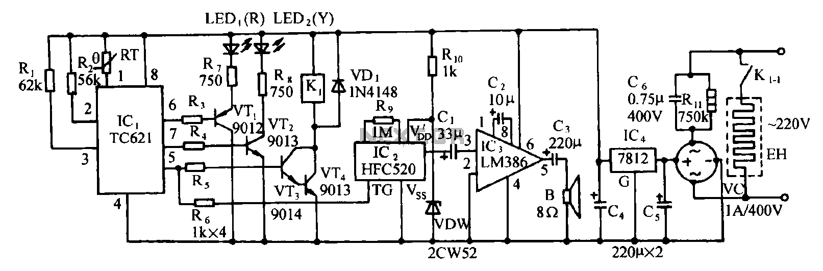
Eggs hatch chicks at temperature requirements within the range of 36 to 39 degrees Celsius. The temperature sensor integrated circuits utilize the TC621 temperature control circuit, which has fewer external components, is low cost, and offers high reliability. Users...
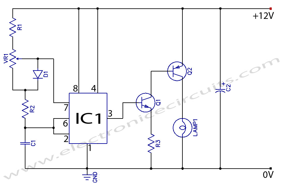
When the potentiometer is in the upper position, the capacitor charges rapidly through both 1k resistors and the diode, resulting in a brief positive interval and an extended negative interval, which dims the lamp to near darkness. Conversely, when...

The circuit illustrated below represents a simple thermometer circuit based on the LM335 temperature sensor. This circuit comprises two main components: the LM335 sensor and its adjustment circuitry. The output from the LM335 generates a voltage of 10 millivolts...
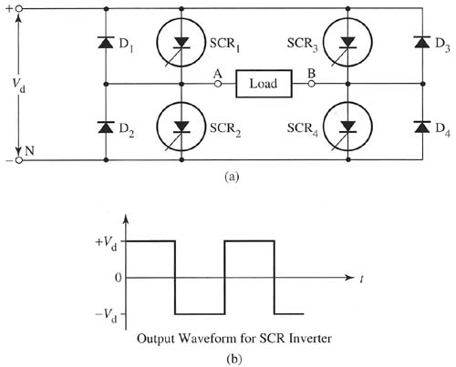
The simplest inverter to understand is the single-phase inverter, which converts a DC input voltage into single-phase AC voltage. The main components of the inverter can be either four silicon-controlled rectifiers (SCRs) or four transistors. A typical inverter circuit...
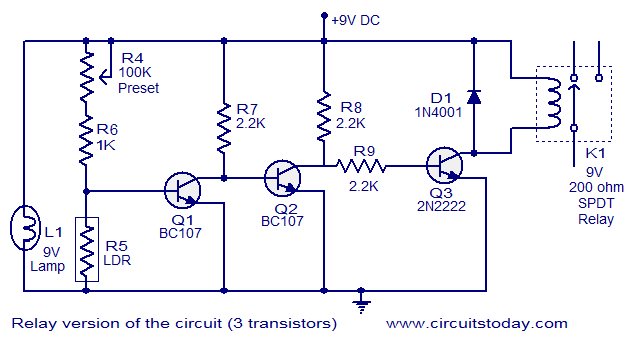
This document describes a simple fire alarm circuit utilizing a Light Dependent Resistor (LDR) and lamp combination for fire detection. The alarm activates by detecting smoke generated during a fire. When smoke is present, the circuit triggers an audible...
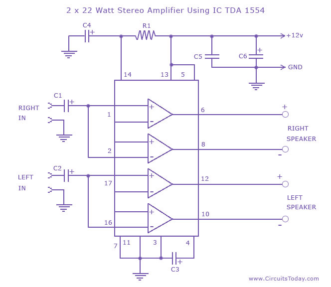
A high-quality stereo amplifier circuit of 44 Watts (22 Watts per channel) using the TDA 1554 IC. This is a powerful audio amplifier circuit for 2 channels. The described stereo amplifier circuit utilizes the TDA 1554 integrated circuit (IC), which...